


Registering Images
295
• Bilinear
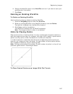
Use this transform to correct an image that appears tilted so that lines
that should be parallel appear to converge; for example, if the data is
in a conic projection. Use the control point tool to associate points on
the layer to register (left window) with corresponding points on the
primary map (right window). Two control points are required at or
near opposite corners of the dataset.
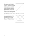
• Polynomial 2d Order
Use this transform when objects in the image appear curved, such as
when a page is scanned from a bound book near the binding. Use the
control point tool to associate points on the layer to register (left
window) with corresponding points on the primary map (right
window). At least three control points are required. Undesirable
interpolation effects are likely for data points that fall outside the
cluster of control points. Consider placing control points around the
border of the data to register, then adding interior points.
• Polynomial 3d Order
Use this transform when the image to register contains a more
complex curve. Use the control point tool to associate points on the
layer to register (left window) with corresponding points on the
primary map (right window). At least 10 control points are required.
Undesirable interpolation effects are likely for data points that fall
outside the cluster of control points. Consider placing control points
around the border of the data to register, then adding interior points.
Depending on how the layer to register is distorted, the control points
may define a solution with more curves than required to correct the
distortion. If this occurs, consider using the second order polynomial
or triangulated transform.
9. Click in the image window to place a point.
A point displays on the image with a label for the point number (the label
"Point" with a number is the default label).
Note For helpful hints on placing points, see Hints for Placing Points.
10. Move your cursor to the map window. Center the cursor over the same
intersection location you chose in the image window and click that same point
in the map window.
OR
If you know the coordinates for the intersection point in the map window,
enter the latitude and longitude numbers in the Latitude and Longitude
fields for the current point.
11. Repeat steps 9–10 for each additional point, evenly distributing points
throughout the image. The number of points that are required varies
depending on the solution you chose in step 8.
12. Optional. If you want to register a portion of the image, click the Crop tool
and draw a polygon around the area you want to crop out of the image.
13. Optional. If you want to make an area in your image transparent, click the
Transparency button
to switch to the transparent image mode. Then
click the area within the image that you want to make transparent when
displayed on the map. To alter the tolerance of the transparency, select