Using the Draw Tools
263
2. Click the Draw tab.
3. If the track you want to edit is not in the active draw file, click File and select
the draw file from the draw file dialog area. Then, click Done.
4. Click the Select tool
and click the track you want to edit.
• A box displays around the selected track.
• The shape points used to create the line display as small, magenta
squares.
5. Change any of the track style, color, or weight options of the existing track.
• To edit any label on a track, click the Select tool, select the line twice,
then type the label in the text box that displays next to the track.
• Reshape the track by dragging any of the points in the line to a new
location. When you select a shape point of a line segment within an
active line:
• A small green circle indicates the start end point of the selected
track segment.
• A small red circle indicates the last end point of the selected
track segment.
• Select the Coordinate or the Distance and Bearing/Angle option
and edit their numbers. Click Apply to initiate the changes.
6. Click Done to finish your edit.
OR
Press the ENTER key on your keyboard.
OR
Click outside the object's active box on the map.
Placing a Routable Road, Routable Trail, Line, Arc, or Spline at a
Specific Location
You can place any line object (routable road, routable trail, line, arc, or spline) at a
specific coordinate location.
Note Routable roads require a routable DeLorme dataset. Routable trails require a
topographic DeLorme dataset. For information, visit www.delorme.com or call
DeLorme Direct Sales at 800-561-5105.
To Place a Line Object at a Specific Location
Use the following steps to place your line object at a specific coordinate location.
1. Click the Draw tab.
2. To place a routable road or trail, click and hold the Routable
Road/Routable Trail tool
and select the tool you want.
OR
To place a line/arc/spline, click and hold the Line/Arc/Spline tool
and select the tool you want. Then, select the line, style, width
(if available), and color for your line/arc/spline.
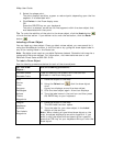
3. Select the Coordinate option, or use the Distance and Bearing/Angle
option in conjunction with the Coordinate option, and enter the appropriate
coordinates or numbers into the corresponding text boxes to the right of the
text style options box.


