


Chapter 3 Hardware Setup 75
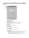
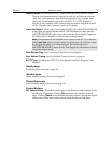
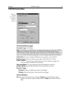
Readout Mode:
The selections are Full Frame (entire chip can be read out) Frame
Transfer (only unmasked area of chip can be read out) and Interline (provides
100% duty cycle operation). Note that frame transfer is only available if the
camera has a frame-transfer chip such as the EEV 512 × 1024. Similarly,
Interline is only available with a camera having an interline chip such as the PI
1030 × 1300 and if the Controller Version is 3 or higher.
Logic Out Output:
Allows you to select either NOT SCAN or SHUTTER MONITOR
as the signal provided at the MicroMAX’s SCAN Output. In Gated operation
SHUTTER MONITOR is the correct choice and the signal should be applied to
the inhibit input of the pulser to prevent pulsing during readout.
Note:
This parameter is not available for all versions of the ST-133 Controller.
If the
Logic Out
selection doesn’t appear on the tab page, the selection is done
by changing the setting of an internal jumper. The default selection is
SHUTTER MONITOR. Contact factory Tech Support for information on how to
change the jumper setting.
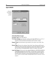
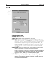
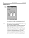
User Defined Chip:
See User Defined Chip discussion on page 80.
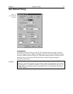
User Defined Timing:
See User Defined Timing discussion on page 81.
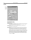
RS170 Type:
Selections are NTSC (US video standard) and PAL (European video
standard).
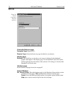
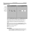
Display page
See Display Page discussion on page 82.
Interface page
See the Interface tab page discussion on page 83.
Cleans/Skips page
See Clean/Skips tab page discussion on page 224.
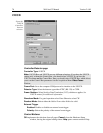
Control Buttons:
OK, Cancel & Help:
These three buttons apply to the Hardware Setup window and are
available for all tab pages. Clicking
OK
implements the selections from all
pages. Clicking
Cancel
closes the Hardware Setup window, leaving the original
settings intact. Help opens context-sensitive help for the active tab page.