


Chapter 15 Menus and Dialog Boxes 259
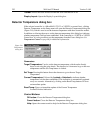
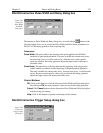
Accumulations can be set on the DG-535 Pulse Sequence Setup dialog box and on the
Experiment Setup Main tab page. The two settings must be the same for proper
operation.
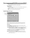
Pulse Width:
The starting and ending pulse widths are independently set. The first
Shot will have the
Starting
pulse width and the last Shot will have the
Ending
pulse width. This is true for both the Fixed and Exponential increment type.
Pulse Delay:
The starting and ending pulse delay values are independently set. The
first Shot will be taken at the
Starting
delay with respect to T
0
and the last Shot will
occur at the
Ending
delay with respect to T
0
. This is true for both the Fixed and
Exponential increment type.
Although the T
0
output of the DG-535 marks the start of each DG-535 timing cycle, the
precise timing of both the gate and signal at the camera will additionally depend on a
number of different delay mechanisms that can significantly affect the experiment.
These are discussed for the PI-MAX camera in some detail in Tips and Tricks chapter of
the PI-MAX instruction manual.
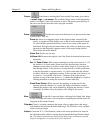
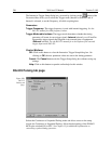
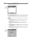
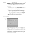
Check Pulse Width and Delay Min/Max (Message Displayed):
If this box is
checked and you specify a pulse width or delay outside the allowable range, a
warning message (Figure 225) will be displayed. Clicking
Yes
will cause the
parameter in question to be set to the limit value. Clicking
No
will cause the
parameter setting to be retained, but the actual value will still be the applicable
minimum or maximum. If the box isn’t checked, the applicable minimum or
maximum will be established automatically.
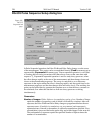
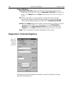
Fixed Increment Type:
With this selection, the increment or change in Pulse Width
and Pulse Delay is the same from shot to shot. The actual increments depend on the
specified starting and ending values and on the Number of Images. The increment
values are calculated and reported in the associated text boxes.
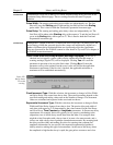
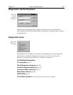
Exponential Increment Type:
With this selection, the increment or change in Pulse
Width and Pulse Delay changes from shot to shot. The precise delay and width of
each shot with respect to T
0
is determined by the values entered for the Fast Decay
and Slow Decay
Time Constant
and
Amplitude
parameters. In fluorescent decay
experiments, for example, there will typically be two species contributing to the
output data, one of which decays much faster than the other. For example, there
might be a fast fluorophor with a decay time of at most a few nanoseconds, and a
slower one with a decay time of perhaps a hundred nanoseconds. By sweeping both
the delay and the width, and making provision for entering time constant and
amplitude information for two species, the sequential exponential algorithm is
ideally suited to making this type of measurement. At the start of the decay where
the amplitude is high but the decay is rapid, the gate pulses are narrow and close
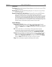
ATTENTION
ATTENTION
Figure 222.
Range Limits
Exceeded
warning.