


366 WinView/32 Manual Version 2.4.M
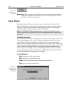
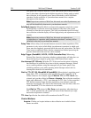
Timer:
The right-most pane is the Data Collection Timer. During an acquisition, it
reports the elapsed time since initiating the run. Otherwise it reports the
computer clock time. Clicking on this pane allows you to toggle the count up or
down.
Temperature
See
Detector Temperature dialog box
on page 252.
Threshold and Clipping
General discussion:
Chapter 11.
Input tab page:
pg. 286
Parameters tab page:
pg. 315
Output tab page:
pg. 307
Thresholding
See
Processes tab page
discussion on page 331.
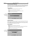
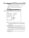
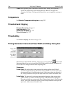
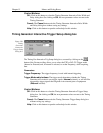
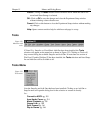
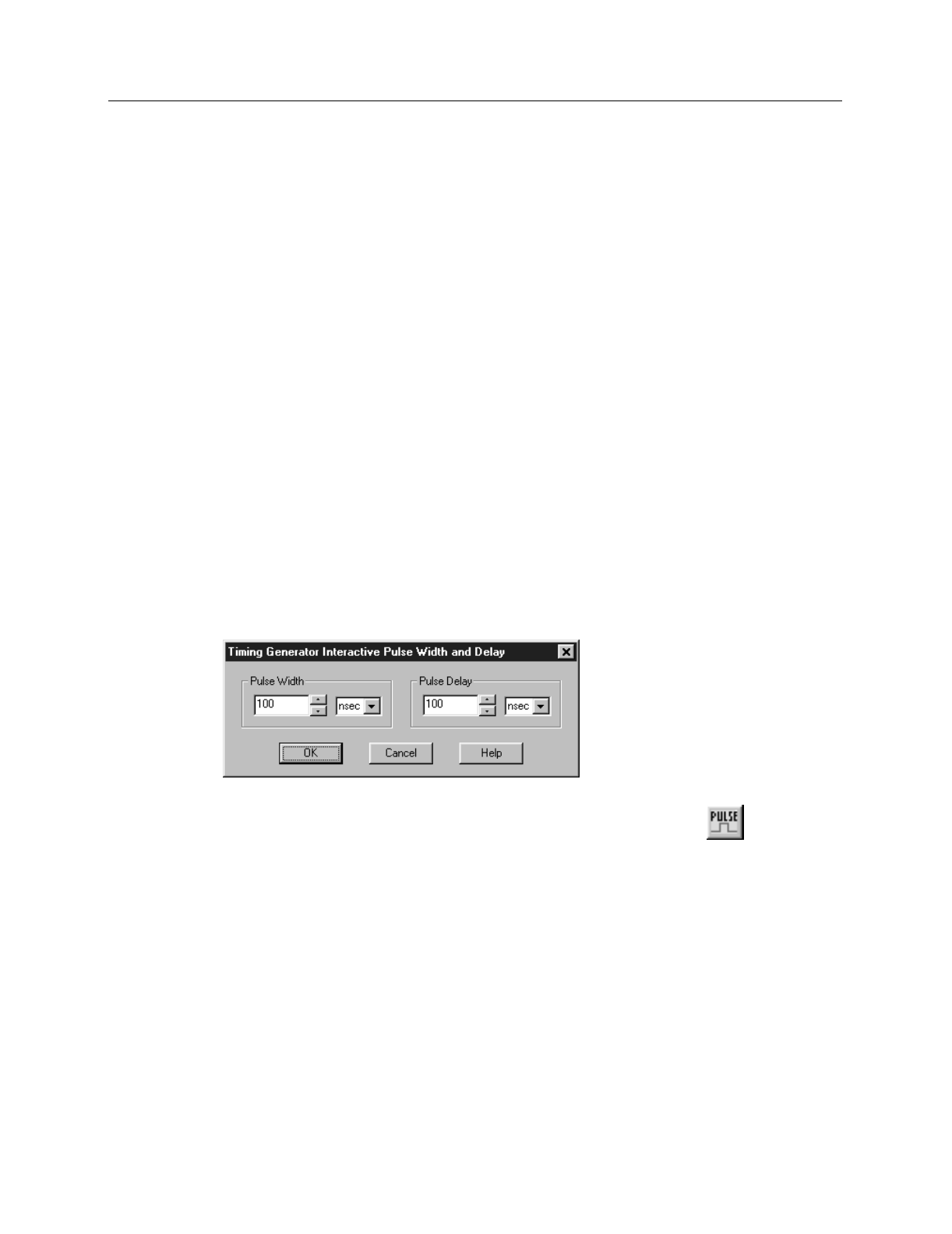
Timing Generator Interactive Pulse Width and Delay dialog box
The Interactive Pulse Width and Delay dialog box, accessed with the button of the
Custom toolbar, allows you to control the Pulse Width and Pulse Delay parameters of a
PTG or DG-535 Timing Generator while acquiring data.
Parameters
Pulse Width:
The pulse width is the duration of the pulse applied to the PI-MAX
intensifier to gate the photocathode. The units available are nanoseconds (nsec),
microseconds (µsec), or milliseconds (msec). Only some values are allowed, so
the Timing Generator will adjust the input value to the nearest allowable value.
Pulse Delay:
The pulse delay is the time between the beginning of the trigger pulse
(either internal or external) and the beginning of the photocathode gate pulse.
The units available are nanoseconds (nsec), microseconds (µsec), or milliseconds
(msec). Only some values are allowed, so the Timing Generator will adjust the
input value to the nearest allowable value.
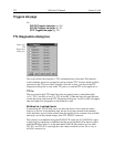
Figure 329.
Timing
Generator
Interactive
Pulse Width
and Delay
dialog box.