


234 WinView/32 Manual Version 2.4.M
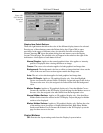
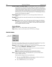
Control Buttons:
OK:
Executes the selections for all tab pages and closes the dialog box.
Cancel:
Closes the dialog box without executing any changes.
Help:
Opens context-sensitive help for whichever tab page is on top.
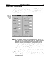
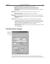
Controller Registers dialog box
See discussion of the
Diagnostics: Controller Registers dialog box
on page 264.
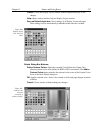
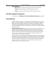
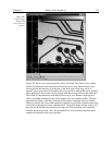
Cross-Sections
Whether displayed as an image or 3D Graph, data can be displayed with cross-section
profiles. Cross-section profiles are not available if the data is displayed as a simple two-
dimensional graph. If the data is displayed as an image as shown in Figure 206, the
vertical cross-sectional profile shows the intensity vs. strip number along the vertical
crosshair and the horizontal cross section shows the intensity vs. pixel number along the
horizontal crosshair.
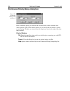
Cross-section tick marks:
The min and max values for each cross section profile are
indicated. These values are only displayed if the axes are also turned on. They are
displayed at the left of the horizontal profile and below the vertical profile. Both axes
and cross-sections must be ON for the minimums and maximums to be shown. Each
time the cursor is moved, the cross-sectional display will change. Clicking on the
Autoscale button will restore full-range scaling.
Note that the axes, as well as the boundary of each profile display area, can be dragged
to change the size of the profile display areas. Each time this is done, click the autoscale
button to restore proper scaling. In general, it is best to use the Large Cursor (selected
via the View men) when displaying cross sections because the large cursor allows the
crosshair coordinates to be precisely read from the scaled axes. See Chapter 6 for
additional information on displaying the data.