


184 WinView/32 Manual Version 2.4.M
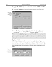
➧ Set the
Aux Trigger
output to be synchronized to either the
Trigger
or the
Gate
pulse.
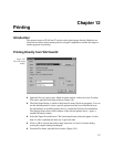
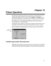
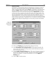
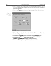
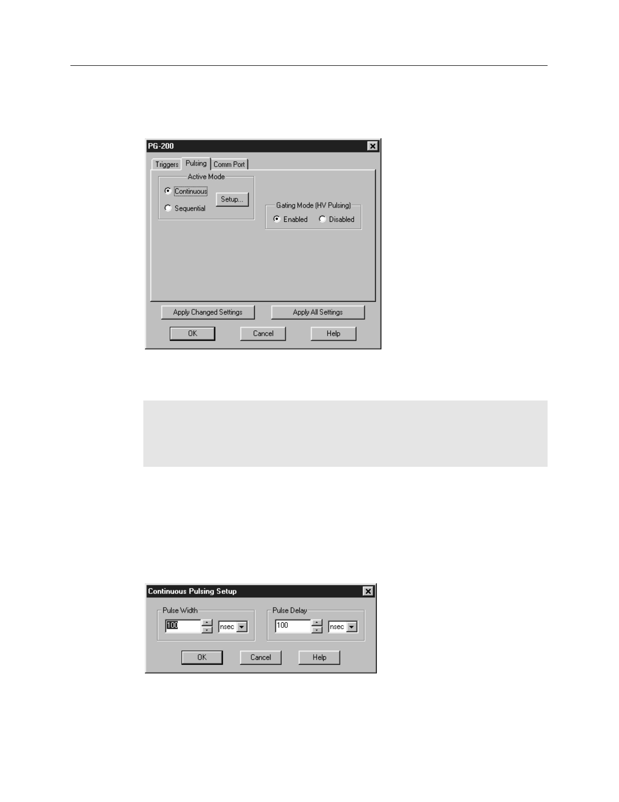
➧ Click on the
Pulsing
tab to bring the Pulsing tab page to the front (Figure 161).
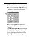
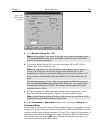
➧ Select
Continuous
or
Sequential
and then click on the adjacent
Setup
button.
For safety, the
Gating Mode (HV Pulsing)
selection should be
Disabled
.
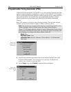
Note:
In setting the PG-200 pulsing parameters, whether for Continuous or Sequential
operation, see your PG-200 Manual for pulse width and delay limitations. Note that gate
pulses are capacitively coupled in many Princeton Instruments intensified detector
heads, so high duty cycles and pulse widths longer than 1 ms may lead to reduced gating
efficiency.
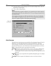
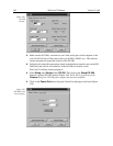
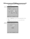
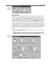
Continuous Mode
If
Continuous
is selected, the Continuous Pulsing setup dialog box will appear as
shown in Figure 162. In the Continuous pulsing mode, the Pulse Width and Pulse Delay
remain constant over the course of the measurement. See page 228 for additional
information. Set the Pulse Width and Pulse Delay to the desired values and click on
OK
.
The Continuous Pulsing Setup dialog box will close and you will return to the PG-200
window.
Figure 161.
PG-200
Pulsing tab
page.
Figure 162.
Continuous
Pulsing Setup
dialog box.