


Chapter 15 Menus and Dialog Boxes 233
charge will be transferred. If too slow, image smearing will be increased due to
the exposure that takes place while the transfer is in progress. The default value
gives good results in most measurements.
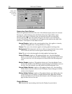
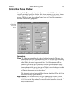
User Defined Chip:
Selecting User Defined Chip makes the Custom Chip tab page
appear. The Custom Chip tab page is described in detail on page 80. Perhaps the
most important thing to keep in mind is that the default values conform to the
physical layout of the CCD array and are optimum for most measurements.
User Defined Timing:
Selecting User Defined Timing makes the Custom Timing tab
page appear. The Custom Timing tab page is described in detail on page 81.
Roper Scientific does not encourage users to change the chip timing settings. For most
applications, the default settings will give the best results. Changing them can adversely
affect performance, sometimes in subtle ways that will not be immediately obvious. We
strongly advise
contacting the factory for guidance before customizing the chip timing
parameter settings.
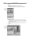
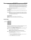
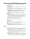
LOGIC OUT Output:
In a PentaMAX, determines the signal provided at the back
panel Logic Out connector. In a MicroMAX or ST-133, determines the signal
provided at the SCAN connector. Selections with an ST-133 or MicroMAX are
Shutter Monitor and Scan only. In some ST-133s, the selection cannot be made
via software but must instead be made by means of an internal jumper. In the
PentaMAX, all of the following are provided.
Cleaning:
TTL Logic 1 during cleaning cycle.
Logic 0:
TTL Logic 0
Logic 1:
TTL Logic 1
Not FT Image Shift:
TTL Logic 0 during frame-transfer image shift.
Not Ready:
After a Start Acquisition command, this output changes state on
completion of the array cleaning cycles that precede the first exposure.
Initially high, it goes low to mark the beginning of the first exposure. In free
run operation it remains low until the system in halted. If a specific number
of frames have been programmed, it remains low until all have been taken,
then returns high.
Not Scan:
TTL 0 when reading out the array.
Shutter:
TTL 1 when the shutter is open.
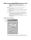
Following parameters only apply with V/ICCD or V/ICCD Control Box
Comm Port:
Set to the computer COM port used to interface to the V/ICCD.
Frame Grabber:
Used to select Serial or Data Translation (3152), whichever
applies.
Waveform Mode:
Select Gate for gated operation. Otherwise select CW.
Readout Mode:
Selects either the Odd or Even video field to be valid.
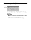
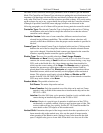
External Trigger
Enabled:
Enables or disables an external event trigger.
Polarity:
Selects the polarity of the external event trigger (if enabled).
CAUTION