


372 WinView/32 Manual Version 2.4.M
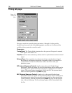
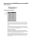
Triggers tab page
See:
DG-535 Triggers tab page:
pg. 262.
PG-200 Triggers tab page:
pg. 323.
PTG Triggers tab page:
pg. 343.
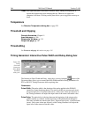
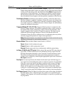
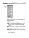
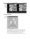
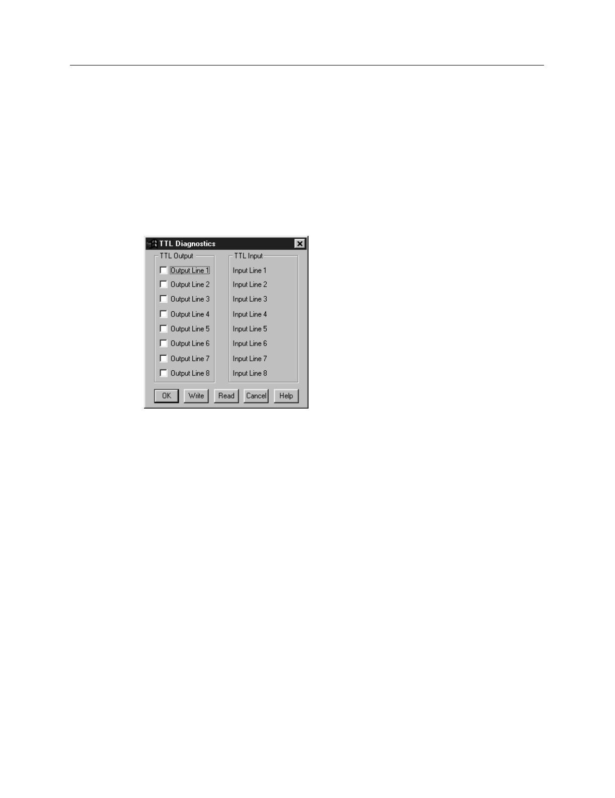
TTL Diagnostics dialog box
This screen allows the Controller’s TTL communications to be tested. This function
would ordinarily be used in conjunction with an external TTL Test box which would be
connected to the TTL port of the Controller. Once this is done, you can use the TTL
Diagnostics dialog box to write to the TTL port or to read the TTL levels applied to it.
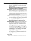
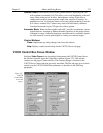
TTL In
The user controls the 8 TTL Input lines from an external source, setting them high
(+5 V; TTL 1; bit ON) or low (0 V; TTL 0; bit OFF). When the lines are read, the state
of each bit can be read from the TTL Diagnostics dialog box. An ON or OFF will appear
after each Input Line designation to show that bit’s state.
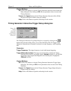
Buffered vs. Latched Inputs
In controlling the TTL IN lines, users also have the choice of two input-line states,
buffered or latched. In the buffered state, the line levels must remain at the intended
levels until they are read. In the latched state, the applied levels continue to be available
until read, even if they should change at the TTL IN/OUT connector.
This control is accomplished using the EN/CLK TTL input (pin 6). If EN/CLK is open
or high, buffered operation is established and the levels reported will be those in effect
when the READ is made. If, on the other hand, EN/CLK were made to go low while
TTL IN 1 and TTL IN 2 were high, the value values would be latched for as long as
EN/CLK remained low.
Figure 334.
TTL
Diagnostics
dialog box.