


292 WinView/32 Manual Version 2.4.M
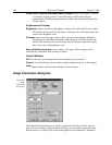
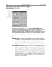
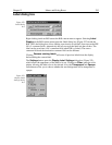
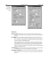
Zoom (ver 5 or higher):
The 1× setting indicates that the CCD image will be binned
or decimated so that the video monitor shows the entire CCD image at reduced
resolution. The 2× setting shows a portion of the CCD image, but at
approximately 1:1 resolution. Since you cannot see the entire CCD image, the
Pan feature becomes available. The 4× setting uses pixel replication to zoom in
and enlarge a smaller region of the CCD image. The availability of the Zoom
and Pan functions depends on the array size relative to the size of the video
display (756 × 486 for RS170; 741 × 576 for CCIR). Note that it isn’t necessary
to close the dialog box for the changes to take effect.
Pan (ver 5 or higher):
The Pan box allows you to select which area of the CCD image
you would like to view on the video monitor. It is available in the 2× or the 4×
mode. Changes to the Pan box are effective immediately if the camera is
running.
Binning (ver 5 or higher):
In the 1× mode, pixels can be binned or decimated to fit
the image from a large CCD chip onto the video display. For low light level
experiments, the Binning option is recommended.
Decimation (ver 5 or higher):
In the 1× mode, pixels can be binned or decimated to
fit the image from a large CCD chip onto the video display. Do not use
decimation if you have very low light levels.
Control Buttons:
Run:
Click on
Run
to begin Interactive operation.
Stop:
Click on
Stop
to end Interactive operation.
Close Button:
Closes the dialog box and saves the setting changes.
Cancel:
Click on
Cancel
to exit the Interactive Operation dialog box without
saving the changes.
Help:
Click on this button to open the online help for this dialog box.
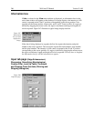
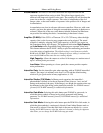
Interactive Trigger Setup
See Timing Generator Interactive Trigger Setup discussion on page 367.
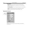
Interactive Pulse Width and Delay
See Timing Generator Interactive Pulse Width and Delay discussion on page 366.
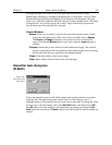
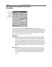
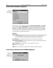
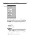
Interface tab page
The Interface tab page, accessed by selecting Hardware on the Setup menu, is used to set
the data transfer communications parameters. See page 83 for a detailed discussion of
this page.