


Chapter 13 Pulser Operation 191
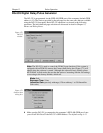
DG-535 Digital Delay/Pulse Generator
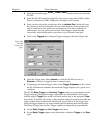
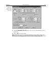
The DG-535 is programmed via the IEEE-488 GPIB port of the computer (default GPIB
address is 15). The choices provided by the tab pages are the same ones that are available
using the DG-535 front panel. Basic DG-535 operation is reviewed in the following
procedure. The individual tab page selections are discussed in detail in Chapter 15,
Menus and Dialog Boxes.
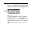
Note:
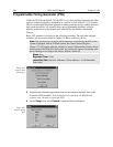
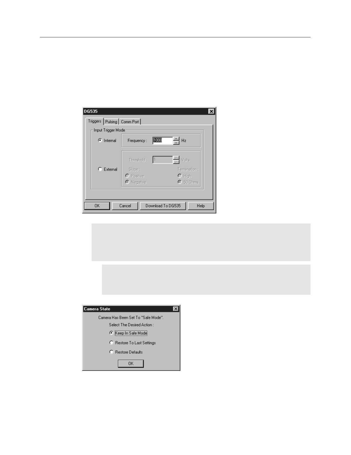
The DG-535 is used to control the PI-MAX gate functions. If the system is
equipped with an PI-MAX camera, the Camera State dialog box (Figure 173) will
appear when the software is started. Although the software always initially places
the PI-MAX in Safe mode, the user has the option of restarting with the last settings
or reverting to the factory defaults, which are:
Mode:
Safe
Exposure Time:
10 ms
Intensifier Gain:
precisely midrange (128 on arbitrary 1 to 256 Intensifier
Gain scale).
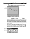
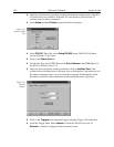
➧ Make sure the DG-535 is connected to the computer’s IEEE-488 GPIB port. Later
you will tell WinView/32 the DG-535’s GPIB address. The default setting is 15.
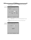
Figure 172.
DG-535
window.
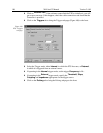
Figure 173.
Camera State
dialog box.