


Chapter 15 Menus and Dialog Boxes 379
that the file WXvchip.opt be present in the same directory as the executable
WinView/32 program. Contact Tech Support for information regarding the
availability of Wxvchip.opt.
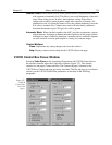
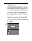
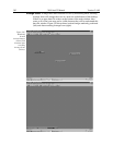
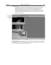
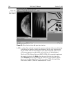
This method of data acquisition requires that the chip be masked as shown in Figure 341.
The mask can be a static one (fixed dimensions) in which case, multiple masks should be
made to accommodate a variety of imaging conditions. Alternatively, a more flexible
mask can be manufactured by taking two thin metal sheets with a square hole the size of
the exposed region of the CCD cut in the center. This would be 512 x 512 pixels at 15
microns per pixel = 7.68 mm x 7.68 mm for the non-intensified PentaMAX. For
cameras with a fiber-optic taper, the aperture will have to be larger since the intensifier
is coupled via a taper with a net reduction. These masks should be anodized black to
prevent reflections in the optical system and they should be very flat. These two sheets
can then be slid relative to one another to achieve any rectangular shape required. The
sheets should be placed flat in the optical plane and their openings should be centered on
the optical axis. Ideally they should be able to move with an accuracy of 2-3 pixels per
step (30-45 microns for non-intensified and 46-70 microns in the intensified PentaMAX)
in the X and Y directions.
In operation, images are continually piped down the CCD at extraordinarily high rates.
The mini-frame transfer region is defined by an ROI as illustrated in Figure 341. The
charge from this ROI is shifted under the frame-transfer mask, followed by a readout
cycle of an ROI sized region under the mask. Since the ROI is far from the serial
register, the stored image is just shifted repeatedly with the read out and the first few
images collected will not contain useful data. After the readout period (which is also the
exposure period), the next frame is shifted under the mask and another ROI sized frame
is read out. The net result is a series of images, separated by spacer regions, streaming up
the CCD under the mask.
Shift Register
ROI
Virtual
Chip
Frame Transfer Mask
Virtual Chip Mask
Virtual
Chip
Mask
Figure 341.
Virtual chip
functional
diagram.