


Chapter 7 ROI and Binning Options 137
Definition of multiple regions
Multiple ROIs can be defined. The number of ROIs stored is given by the Number
Stored indication. The Edit Pattern data box allows any stored pattern to be selected and
its parameters changed. The Start, End and Group values for the selected pattern are
displayed. To add another pattern to those already defined and stored, the Edit Pattern
must be set to one higher than the indicated Number Stored. When this is done, “Edit
Pattern” changes to “New Pattern,” indicating that the parameter values for the pattern to
be added can be entered.
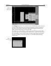
In defining multiple ROIs, there is one constraint that must be observed, and that is that
ROIs cannot overlap. This places restrictions on the Y values that can be specified. For
example, if Pattern 1 had a Y Start value of 1 and a Y End value of 100, the Start value
for the next ROI would have to be greater than 100. If a Full pattern is selected and
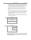
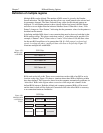
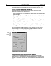
stored, it overlaps all others, causing all data collections to be full-chip. Figure 123
illustrates multiple full-width ROIs.
ROI Pattern #1
CCD Chip
ROI Pattern #1
ROI Pattern #2
ROI Pattern #3
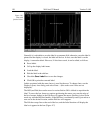
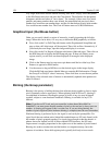
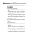
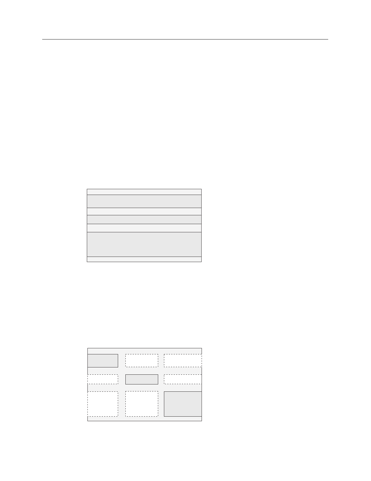
ROIs need not be full width. There are no restrictions on the width of an ROI or on its
location on the chip. Figure 124 shows a situation where three ROIs of differing widths
have been defined. This figure also shows how the computer automatically generates six
“side-effect” ROIs in the regions where extensions of the strips and columns of the
defined ROIs intersect. Both the defined and computer generated ROIs will be stored
and the data for both will be displayed. Generation of the side-effect ROIs is necessary
to accommodate hardware limitations.
CCD Chip
defined ROI
defined ROI
defined ROI
computer ROI
computer ROI
computer ROI
computer ROI
computer ROI
computer ROI
Figure 123.
Multiple full-
width ROIs.
Figure 124.
Multiple ROIs
with different
widths.