


Chapter 15 Menus and Dialog Boxes 213
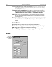
Rate:
The selected rate is displayed in the box. Clicking on the button at the right of the
box drops the list of the available rate selections for the selected ADC to be
displayed so that another setting can be selected. Note that not all ADCs offer
multiple rates. With an PI-MAX camera, selecting FAST on the A/D page
causes the High Capacity preamplifier node to be selected. Conversely, selecting
SLOW on the A/D page causes the Low Noise preamplifier node to be selected.
The node selection is indicated on the Main page.
Resolution:
The selected resolution in bits is displayed in the box. Clicking on the
button at the right of the box drops the list of the available resolution selections
in bits for the selected ADC to be displayed so that another setting can be
selected. Note that not all ADCs offer multiple resolutions.
Controller Gain (PentaMAX only):
Displays the controller gain setting. Clicking the
button drops down the list of available gain settings so that the setting can be
optimized for your particular experiment. Gain 3 is the default setting and gives
good results in most measurements.
Bit Adjust (ST-138 only):
When reading out data from a 16 bit ADC, the user can
choose to discard data bits. If the data is low level, never reaching more than
30,000 counts, then the top bit (the most significant bit or MSB) can be
discarded. If the sensitivity at the low end of the detector is not important, then
one or two least significant bits can be discarded.
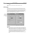
ADC Offset (5 MHz MicroMAX only):
The 5 MHz MicroMAX (ST-133) controllers
used with the interline cameras employ a programmable DAC (Digital to Analog
Converter) to set the offset.
*
The adjustment can be set directly from software
beginning with the release WinView/32 ver 2.2. In early 5 MHz controllers, the
Offset value must be reset at the start of every new software session, change in
ADC selection, or if a different offset is desired. In later units, the most recently
set Offset value will be stored in non-volatile RAM located in the controller
making it unnecessary to change the setting at the start of every software
operating session.
Note:
There is no recommended offset value at present. It is suggested that
adjustments in increments of 50 be used until the mean offset under dark, short
exposure conditions is in the range of 10-50 counts. Fine tuning is not essential.
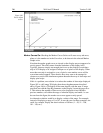
Setting the offset to compensate for long-exposure dark current or to compensate
for high signal levels is not recommended, due to the 'apparent' loss of linearity
(shown with zero intensities on low, non-zero light levels).
There is no calibration or meaningful units on the Offset parameter Value,
although it tracks the reported counts fairly closely.
Control Buttons:
Acquire:
Clicking on Acquire initiates a data-collection run in which all data frames are
stored.
*
This function was previously performed on the standard MicroMAX with the 'F' and 'S'
adjustment screws on the Analog Module panel.