


238 WinView/32 Manual Version 2.4.M
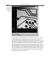
None (no cursor displayed). The cross-hair cursor, which extends all the way to the
boundaries of the data-display area with an image display, is particularly
advantageous for reading the cursor’s coordinates from the axes scales. Some cursor
functions differ depending on whether image or graphed data is being displayed. For
example, with a 3D Graph display, the appearance of the large cursor in the data area
is the same as for the small cursor. However, if Cross Sections are displayed, a
projections of the large cursor will be displayed on the profiles so that the values at
the cursor position can be read accurately.
Image Display:
Clicking the mouse cursor on the image at any point moves the
data cursor to that point. The left/right arrow keys will move the cursor laterally
and the up/down arrow keys will move it vertically. The Home key moves the
cursor all the way to the left and the End key moves it all the way to the right. If
the Information box is displayed, the cursor coordinates are continuously
reported.
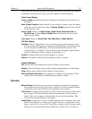
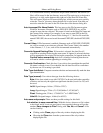
Graph Display:
Single Strip Graph:
The left/right arrow keys move the cursor laterally along
the strip. Clicking the mouse on the display selects a different point on the
same curve. The Home and End keys move the cursor to the strip ends. The
up/down arrow keys select and display a different strip. Shift Home and
Shift End move the cursor to the first strip and last strip respectively. If the
Information box is displayed, the cursor coordinates are continuously
reported.
The Insert key expands the display about the cursor position. The Delete key
contracts the data if it has been expanded, allowing the original display to be
restored.
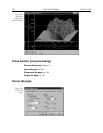
3D Graph:
Same as for single graph except that cursor position is projected
onto cross-section profiles if displayed.
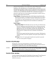
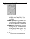
Custom chip tab page
This tab page, accessed by selecting Hardware on the Setup menu, allows user
redefinition of the chip which could be advantageous in certain measurement situations.
See page 80 for a detailed discussion of the Custom Chip tab page.
Roper Scientific does not encourage users to change these parameter settings. For most
applications, the default settings will give the best results. We
strongly advise
contacting
the factory for guidance before customizing the chip definition.
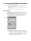
Custom Filter window
Contains the Input tab page (page 286), Filter Matrix tab page (page 276) and Output tab
page (page 307), used to control the Custom Filter function. See Chapter 10 for
additional information.
CAUTION