


138 WinView/32 Manual Version 2.4.M
Any single ROI can be deleted without affecting other ROIs. Simply select that pattern
in the Edit Pattern entry box and press the Clear button. The definition for that pattern
disappears and the ones above it “move down.” For example, if there were five stored
patterns and pattern number three were deleted, the pattern that had previously been
number four would become number three, and the one that had previously been number
five would become number four. The Clear All button removes all ROI definitions.
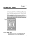
Graphical input (the Mouse button)
Often you can easily identify a region of interest by visually inspecting the full-chip
image. When this can be done, it is very easy to define the ROI graphically as follows.
➧ First, click on the Use Full Chip radio button on the Experimental Setup Main tab
page so that a full-chip image will be acquired. Then click on Run. Alternatively, if
you already have an image, open this image and display it on screen.
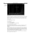
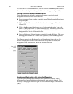
➧ Next click on the Use Region of Interest radio button (Main tab page). Then click on
the ROI Setup tab to display the ROI Setup tab page. If there are already access
regions stored, you will now see them displayed as rectangles in the displayed
image.
➧ Click on the Pattern entry-box up-arrow spin button until the box label says New
Pattern (as opposed to Edit Pattern).
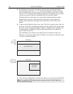
➧ Use the mouse to drag an ROI box over the desired region in the image display.
Click the ROI tab page button labeled Mouse to enter the ROI information. Change
the Group X or Group Y value if necessary. Then click Store to save the new pattern.
The display of the selected areas of interest is automatically updated when patterns are
added or cleared.
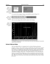
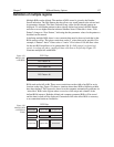
Binning (the Group parameter)
Binning is the process of adding the data from adjacent pixels together to form a single
pixel (sometimes called a super-pixel). When operating with WinView/32, binning is
accomplished in hardware. Rectangular groups of pixels of any size may be binned
together, subject to some hardware limitations. Binning is available for any CCD
detector.
Note:
If you have a PCI card, and your controller is other than a MicroMAX or
PentaMAX, you must ensure that the number of pixels to be read out is always an even
number. A warning will appear if this is not the case. If you are doing binning, the
number of pixels digitized (after hardware binning is complete) must be an even number.
Hardware binning is performed before the signal is read out by the preamplifier. For
signal levels that are readout-noise limited this method improves S/N ratio linearly with
the number of pixels grouped together. For signals large enough so that the detector is
photon shot noise limited, and for all fiber-coupled ICCD detectors, the S/N ratio
improvement is roughly proportional to the square-root of the number of pixels binned.
Binning also reduces readout time and the burden on computer memory, but at the
expense of resolution. Since shift register pixels typically hold only twice as much