


136 WinView/32 Manual Version 2.4.M
➧ For defining only one region for readout, you must make sure that the Number
Stored parameter shows 0 or 1. A “1” indicates that a pattern is already stored and
you are going to edit it. The text window to the left of Number Stored will read Edit
Pattern. A “0” for Number Stored indicates that there is no defined region, in which
case the text window to the left of Number Stored will read New Pattern.
If Number Stored is greater than one, it means that multiple patterns have been
defined. If this is the case, click on the Clear All button to remove them. The
Number Stored parameter will change to 0 and the text box name will be New
Pattern.
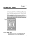
➧ A region can be defined by either of two ways. The first is simply to enter values for
the X and Y Start, End, and Group parameters from the keyboard. The second is drag
the mouse cursor on a displayed image to define a rectangular region and then click
the Mouse button. Graphically defining an ROI using the mouse is explained in
greater detail on page 138.
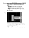
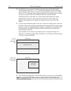
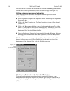
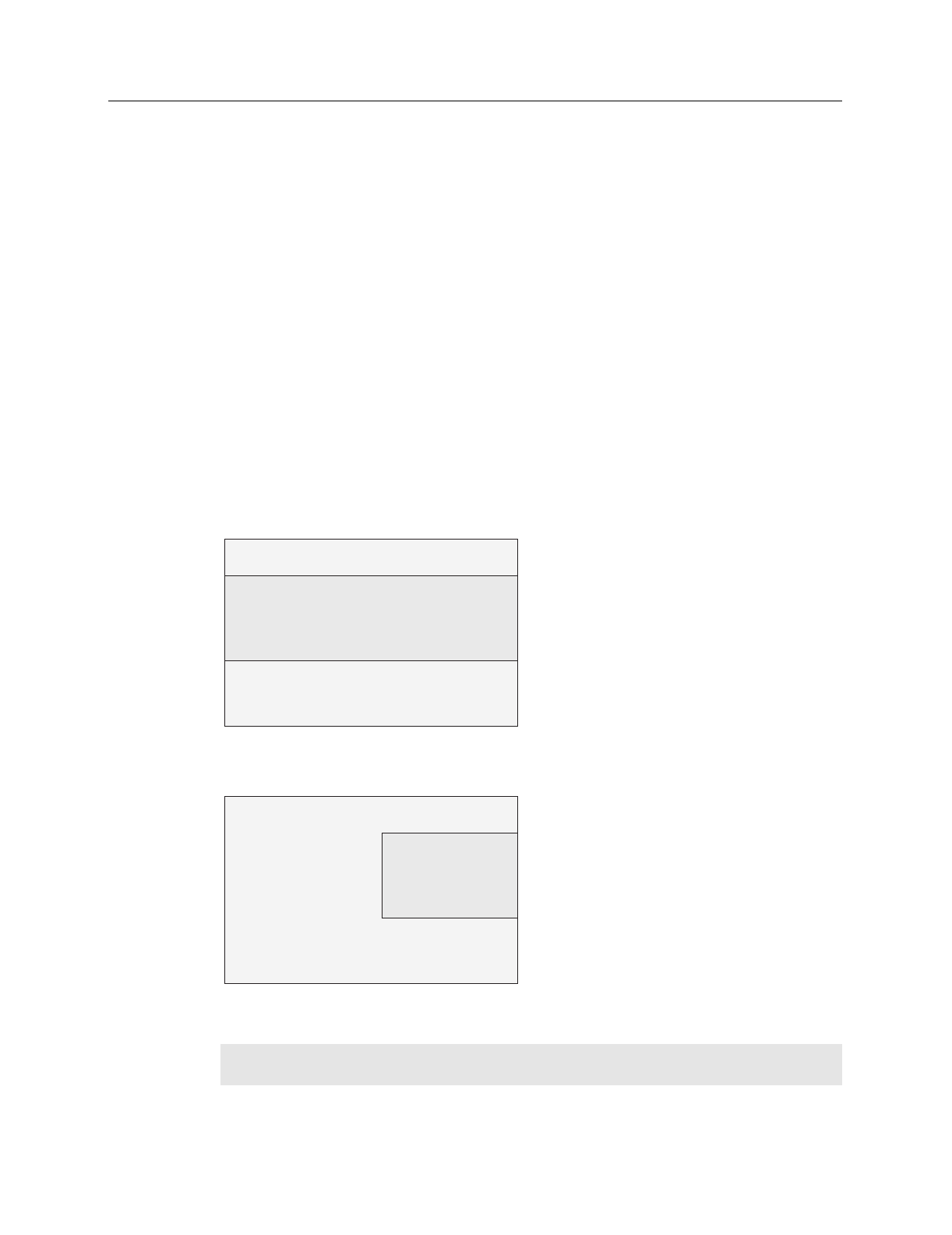
Note that ROIs are not limited to full width like the one depicted in Figure 121.
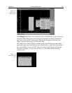
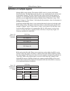
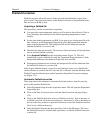
There are no restrictions on the width of an ROI or on its location on the chip. Figure
122 shows a partial-width ROI.
CCD Chip
defined ROI pattern
CCD Chip
partial-width
ROI pattern
➧ After defining the ROI pattern, click the Store button to save the newly defined ROI.
Note:
To scan the full CCD chip at any time, simply click the Use Full Chip radio
button on the Main tab page.
Figure
121. Full-
width single
ROI.
Figure 122.
Partial-width
single ROI.