


Chapter 13 Pulser Operation 183
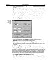
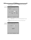
➧ Select the Comm Port type,
Serial
or
Demo
.
Serial
must be selected to control the
PG-200.
➧ Select the PG-200 Comm Port. Generally, the mouse is connected to COM1 and the
Pulser is connected to COM2. COM ports 1 through 8 can be selected.
➧ Once you have selected the correct port, click on
Initialize Port
, which will cause
the software to search for the pulser. If it can’t find the pulser on the specified port,
such as would occur if the pulser were not turned on or if it were connected to a
different port, you will get an error message. If this happens, check the cable
connections, check that the pulser is powered, or try a different Comm port.
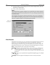
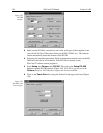
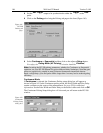
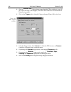
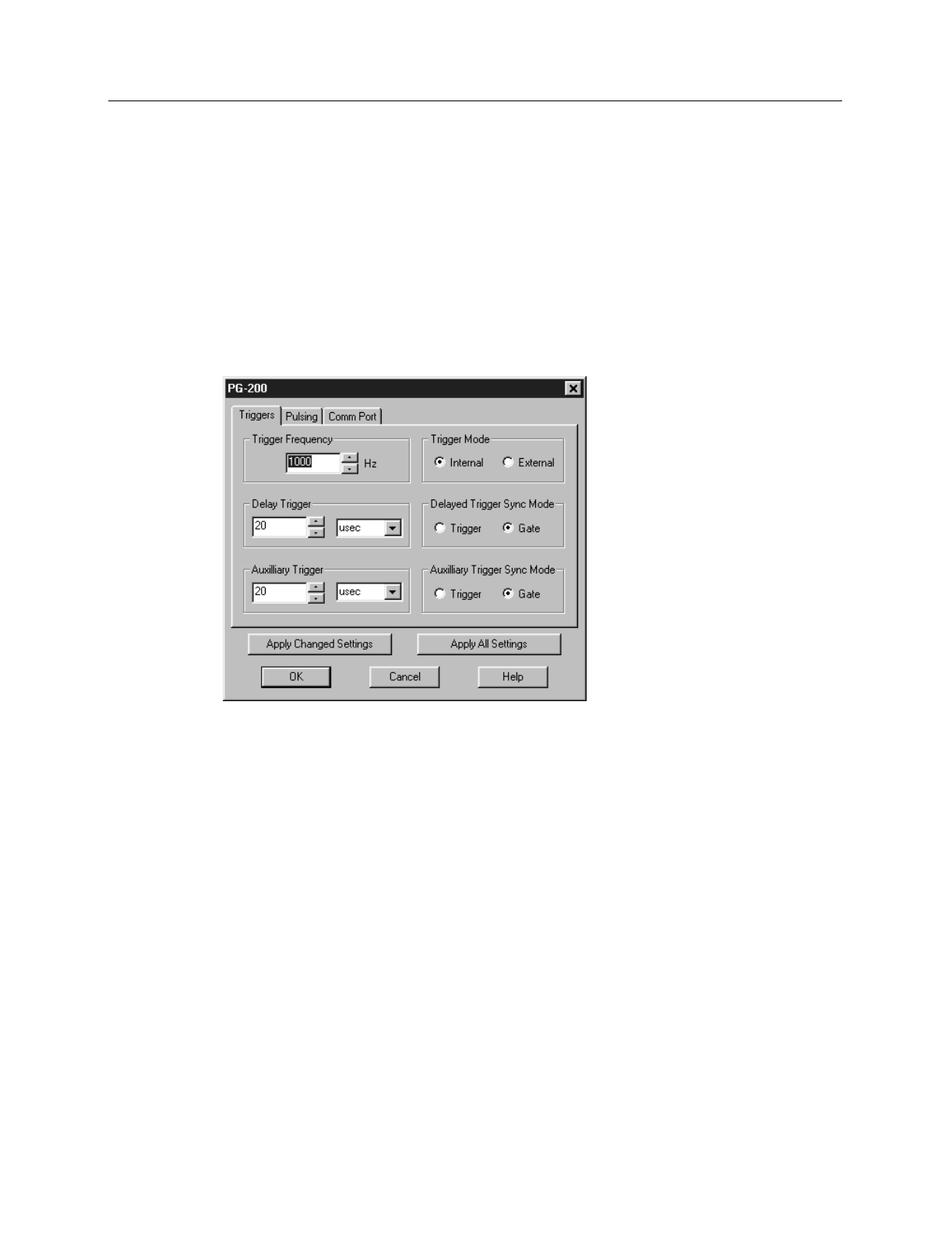
➧ Click on the
Triggers
tab to bring the Triggers tab page to the front (Figure 160).
➧ Select the Trigger mode, either
Internal
, in which the PG-200 free runs, or
External
, in which it is triggered from an external source.
➧ If operating in the Internal trigger mode, set the
Trigger Frequency
in Hz. Consult
the PG-200 Manual to determine the maximum Trigger Frequency for a given set of
conditions.
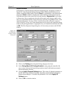
The PG-200
Delay Trigger
and
Auxiliary Trigger
outputs, are programmed from the
Triggers tab page. They produce trigger outputs that are synchronized to and delayed
from the trigger (
Trigger
Sync mode) or from the trailing edge of the gate pulse (
Gate
Sync mode). In the Gate Sync mode, as the gate pulse changes its position and width, the
trigger outputs remain synchronized with the gate, moving with it. In the Trigger Sync
mode, the trigger outputs do not sweep with the gate but maintain their initial position.
The Delayed Trigger and Auxiliary Trigger outputs are independently programmable.
➧ Set the
Delay Trigger
and
Aux Trigger
initial delay.
➧ Set the
Delay Trigger
output to be synchronized to either the
Trigger
or the
Gate
pulse.
Figure 160.
PG-200
Triggers tab
page.