


112 WinView/32 Manual Version 2.4.M
Viewing axes and cross sections
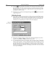
➧ Still in the Display Layout window, select Axes Horizontal, Axes Vertical, Cross
Sections Horizontal and Cross Sections Vertical. Chapter 15 contains additional
information on Axes and Cross Sections.
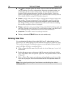
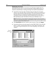
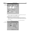
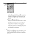
➧ Click on the
Range
tab to move the Range tab page (Figure 91) to the front.
Initial
Autoscale
and
Set to Full Range
should be selected. The Frame number should
be “1.”
➧ Click on the OK button. The Display Layout window will close.
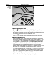
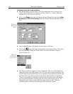
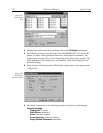
➧ Click on the
(Autoscale) button at the bottom of the image window. Then select
the large cursor by clicking on Cursor on the View menu and then on Large as
shown in Figure 92.
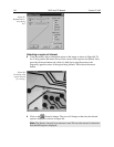
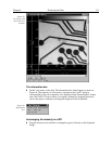
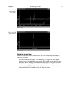
➧ The display should now appear as shown in Figure 93. The axes will be labeled in
image pixels and strips with respect to the CCD chip used to acquire the image. The
vertical image intensity profile at the cursor position will be displayed to the left and
the horizontal image intensity profile at the bottom. The minimum and maximum
values for each profile are indicated. Note that you can use the mouse and drag the
axes and profile boundaries to change the size of the profile display regions. To
change the cursor location simply click the mouse at the new spot. The cross-
sectional graphs will change to reflect the profiles at the new location.
Figure 91.
Range tab
page.
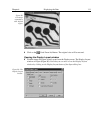
Figure 92.
Selecting the
large cursor.