8: DMA Controller
GP4020 GPS Baseband Processor Design Manual 93
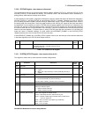
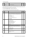
3.1.1) Set to ”1” the DMAC Hardware Request Status bit (bit 1), to allow Hardware requests (dreq and
dack) from the UART to control the DMAC function.
3.1.2) Clear to “0” the DMAC Software Request bit (bit 2), to disable the Software DMA transfer
triggering. Note that when a software trigger is required after the DMAC is programmed, a write
of a "1" to this register bit will initiate a DMA transfer.
3.1.3) Clear to “0” the DMAC Hardware Request Polarity bit (bit 3) and Hardware Acknowledge Polarity
(bit 4), to indicate that the Fly-by Dreq and Dack signals from the DMAC to UARTs 1 and 2 are
active High signals.
3.1.4) Set to “1” the DMAC Hardware Acknowledge Status bit (bit 5), to enable the Dack signals from
UARTs 1 and 2 to indicate when either UART1 or UART2 have been implicitly addressed by the
DMAC.
3.1.5) Clear to “0” the Address Mode bit (bit 6), to allow the single-addressed location in memory to be
dynamically modified between successive DMA transfers. The Address Direction bit (bit 7) should
be set depending on whether the address location should dynamically increment (bit 7 set to “1”)
or decrement (bit 7 cleared to “0”).
3.1.6) Clear to “0” the Transfer Direction bit (bit 8), to signify data is being read from memory.
3.1.7) Clear to “0” the Transfer Mode bit (bit 9), to signify that Data transfers will be Single-addressed
(i.e. Fly-by) between memory and a hardware hand-shaked peripheral (i.e. UART 1 if CSR is for
DMAC Channel 1 and UART 2 if CSR is for DMAC Channel 2)
3.1.8) Clear to ”0” the Transfer Type bit (bit 10) to allow Packet Data Transfers to occur.
Packet Data transfers must be used in Single-addressed transfers with the GP4020 UARTs, as
the UARTs do not have the bandwidth to cope with data transfers at full BµILD bus bandwidth
(28MHz x 4 = 112Mbytes/second). In addition, if running the ARM7TDMI simultaneously with a
DMA transfer, packet transfers of one word per packet will allow the ARM to operate on alternate
bus cycles. DMA Block transfers will stall the ARM7TDMI, which could be fatal in a GPS system
where correlator interrupts MUST be serviced.
3.1.9) Clear to “0” the Request Trigger Type bit (bit 11), to allow enable “Edge-Triggered” Packet
Transfers. Refer to Section 6.2.1.4 in the Firefly MF1 Core Design Manual for details of Edge-
triggered Packet Transfers.
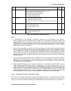
3.1.10) Clear the DMAC Operand Size (bits [13:12]) to zero (i.e. 0y00), to set Byte-wide data in the DMA
transfer. The GP4020 UARTs will cope with byte-wide data only.
3.1.11) It may be desirable to set-up an Interrupt Service Routine to run in the ARM7TDMI to service a
DMAC Interrupt signal into the Firefly INTC Channel 3 (Refer to Section 10 "INTERRUPT
CONTROLLER (INTC)" on page 107 for information on Interrupt settings). The DMAC interrupt
can be generated under the conditions indicated in Section 6.2.3.5 of the Firefly MF1 Core
Design Manual. If the Interrupt into the Interrupt Controller (INTC) in Firefly is required, Set to "1"
the Interrupt Enable bit (bit 16) of the DMAC CSR; if NOT required, Clear this bit to "0".
3.1.12) Clear to “0” the Bus Lock bit (bit 17), to prevent the DMAC from being interrupted during a
transfer from a Higher priority BµILD Bus Master (e.g. ARM7TDMI, SSM)
3.1.13) Clear to “0” the Peripheral Location bit (bit 18), to indicate that the UART peripheral is an Internal
device to the GP4020.
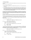
3.2) Set DMAC Packet Size (bits [7:0]) of the Packet Size Register (PSR) to zero (i.e. 0x00). This signifies that
each DMAC data packet will be one word in size.
3.3) Set the DMAC Base Address Register (BAR) with the base memory-location of the data needing to be
transferred to the UART. With the Address Mode set to “dynamic”, this base-address should be an area of
the memory map where there is a contiguous memory space (i.e. SRAM or ROM).


