


7: 12-Channel Correlator
GP4020 GPS Baseband Processor Design Manual 51
7.1.3 Raw-Timemark Generator
The Raw Timemark generator generates two essential signals:
1) CK100kHz. This 100kHz clock is derived from M_CLK. This clock is only as accurate as the receiver TCXO
attached to the RF front-end, and hence cannot be re-synchronised to any GPS system timing. This signal can
be accessed from the Peripheral Control Logic (PCL) block.
2) Raw Timemark. This is a one Pulse-Per-Second (1PPS) signal which is derived the Multiphase Clock and the
TIC signal from the Timebase generator.
The Raw Timemark signal can be aligned to UTC (Universal Time Co-ordinated) by means of dynamic software
skewing of the TIC period within the Timebase Generator. The resolution of the TIC skewing is limited to 175ns
minimum. Improved alignment resolution can be achieved in conjunction with an external block of circuitry, the
1PPS Timemark Generator.
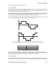
There are two methods of generating the Raw Timemark signal. In both cases TIMEMARK rising edges are
generated coincident with the rising edges of TIC. Therefore, for TIMEMARK to be aligned with UTC, TIC must be
aligned with UTC. This can be done by modifying the TIC period for a single TIC cycle, then setting it back to its
original value, thus slewing the phase of TIC. The alignment to UTC can also be performed independently of TIC
slewing by an independent delay counter within the external 1PPS Timemark generator.
Raw Timemark can be generated using two methods:
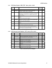
1) Set "FREE_RUN_TIMEMARK" (Bit 1 in TIMEMARK_CONTROL register) to ‘0’ and by setting the
ARM_TIMEMARK bit (Bit 0); the next TIC will generate a rising edge at RAW_TIMEMARK and clear the
ARM_TIMEMARK bit.
2) Set "FREE_RUN_TIMEMARK" to '1', and set the number of TICs per RAW_TIMEMARK period in the
"FREE_RUN_RATIO" bits of the register (Bits 2 to 6). In this instance, a RAW_TIMEMARK output pulse is
generated automatically every "FREE_RUN_RATIO" TICs automatically.
Further details of producing 1PPS Timemark are covered within Section 15 "1PPS TIMEMARK GENERATOR" on
page 149 for more information.
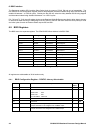
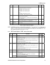
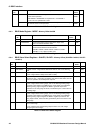
7.1.4 Status Registers
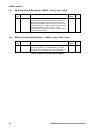
There are four status registers (ACCUM_STATUS_A, _B, _C and MEAS_STATUS_A). These contain flags
associated with the accumulated and measurement data held on each of the 12 channels. Some system level
status bits also appear in these registers.
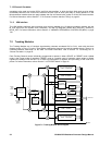
7.1.5 Sample Latches
The Sample Latches synchronise data from the front end to the internal SAMPCLK. The down converted satellite
signal can be sampled at the output of the front end by SAMPCLK. This data is then input to the 12-channel
correlator as 2-bit data on the SIGN0, MAG0, where it is resampled at the next rising edge of SAMPCLK. These
signals are then distributed to the 12 tracking modules. When a GP2015 or GP2010 front end is used, the data
represents a band–limited signal at an IF centred on 4.309MHz. The IFOUT will alias to a 1.405MHz digitised IF, by
sampling the 4.309MHz signal at a rate of 5.714MHz.
7.1.6 Address Decoder
The Address Decoder performs address decoding for the correlator.
7.1.7 Bus Interface
The Bus Interface controls the transfer of data between the external 16-bit wide data bus and the internal 32-bit
data bus. Apart from the code and carrier DCO increment values, all data transfers are 16-bits wide. Write