


GP4020 GPS Baseband Processor Design Manual Index - IX
Table 18.1 Watchdog Register Map.........................................................................................178
Table 18.2 Watchdog CONSTAT Register ...............................................................................179
Table 18.3 Watchdog RELOAD Register .................................................................................179
Table 18.4 Watchdog READ Register......................................................................................179
Table 18.5 Watchdog RESTART Register................................................................................180
Table 18.6 Watchdog TEST Register.......................................................................................180
Table 18.7 Watchdog test signals............................................................................................180
Table 19.1 GP4020 System Address Map................................................................................181
Table 19.2 Truth Table for NSCS[2A] to avoid external reflection of internal accesses, using SADD[19] 182
Table 19.3 GP4020 Memory Area 3 Addressing, with modified NSCS[2A] logic ........................182
Table 19.4 Truth Table for NSCS[2A] to avoid external reflection of internal accesses, using GPIO line 182
Table 19.5 GP4020 Memory Area 3 Addressing, with modified NSCS[2A] logic ........................182
Table 19.6 Firefly MF1 Address Map .......................................................................................183
Table 20.1 GP4020 Pin Types.................................................................................................187
Table 20.2 3.3V Input delays...................................................................................................188
Table 20.3 5V Tolerant Input delays ........................................................................................188
Table 20.4 X01 Slow L1 3.3V Output delays ............................................................................188
Table 20.5 X01 Normal N 3.3V Output delays..........................................................................189
Table 20.6 X01 Normal N 5V Tolerant Output delays ...............................................................189
Table 20.7 X03 Slow L1 3.3V Output delays ............................................................................189
Table 20.8 X03 Normal N 3.3V Output delays..........................................................................190
Table 20.9 Input & Output Cell DC Characteristics...................................................................191
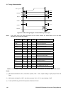
Table 21.1 Simulated Timing parameters for MPC External Transactions with on-chip Wait-state control 194
Table 21.2 Simulated SWait Timing parameters for MPC External Transactions .......................195
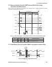
Table 21.3 Simulated DMAC Timing parameters......................................................................196
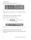
Table 21.4 Simulated Interrupt Timing parameters ...................................................................196
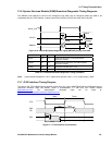
Table 21.5 Simulated Broadcast Diagnostic Timing parameters................................................197
Table 21.6 JTAG Timing parameters .......................................................................................198