


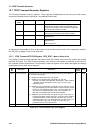
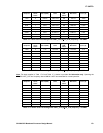
17: UARTs
GP4020 GPS Baseband Processor Design Manual 169
17 UNIVERSAL ASYNCHRONOUS RECEIVER TRANSMITTER (UART)
17.1 Introduction
The GP4020 uses two Universal Asynchronous Receiver Transmitter (UART) modules, which are components that
provide industry-standard levels of support for full-duplex asynchronous serial communications, with appropriate
mechanisms for software flow control. Neither UART1 nor UART2 support flow control with modem handshake
signals (RTS, CTS, DTR, and DSR). Both of the UARTs support DMAC fly-by operation, allowing efficient transmit
and receive transfers.
The UARTs support the following features:
• Full duplex operation, independent transmit and receive channels;
• 7- or 8-bit serial data length;
• 1 or 2 stop bits;
• Even, odd or no parity generation;
• Internal selectable baud rate generator, derived from system clock;
• Double buffered transmit and receive channels;
• Software polling to determine channel status;
• Optional interrupt generation on transmit channel becoming empty or receive channel becoming full;
• Detection of parity, overrun, and framing errors on receive channel, with optional interrupt generation;
• Digital input filter to improve noise immunity
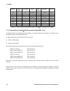
The GP4020 incorporates a standard UART as part of the Firefly MF1 Core and an additional UART that is similarly
configured, except for the following differences:
1) UART1 is clocked by the Firefly BµILD_CLK, which can be disabled by the F_SLEEP function (refer to Section
12.5 "Interrupt and Wake-up logic" on page 121, for more information)
2) UART2 is clocked by the UART_CLK, which is enabled whilst BµILD_CLK is disabled. This allows UART2 to
remain active, while the Firefly Core is "asleep".
3) UART2 produces a Data-received interrupt signal, UART_INT, which can be used as a wake-up trigger for the
Wake-up and Interrupt Logic in the Peripheral Control Logic. UART_INT is derived from the UART2 "Receive
Interrupt" signal, which can be enabled by setting bit 4 of the UART2 Serial Control Register.
The UARTs provide 0V - 3.3V logic levels (not standard RS232 levels). If the UARTs are required to communicate
across RS232 lines, and so will need to interface to RS232 lines via inverting level-shifter components.
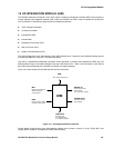
17.2 Baud Rate Generation
The UART transmit and receive channels are clocked from a single, locally derived clock (referred to below as the
internal clock), whose period is determined by the reference clock, and the value programmed into the baud rate
register. The input clock is provided by:
• BµILD_CLK for UART1
• UART_CLK for UART2