


17: UARTs
170 GP4020 GPS Baseband Processor Design Manual
Whilst these are the same frequency, the BµILD_CLK can be disabled by using the F_SLEEP facility (refer to
Section 12.5 "Interrupt and Wake-up logic" on page 121, for more information).
In both UARTs, the clock pre-scaler, 16 bits long, is configured to generate a reference clock of period ‘Sclk divided
by 1, 2, 4, 8, 16, 32, 64, 128, …. upto 32768’, as specified by one of the 16 combinations of value [0000 to 1111]
programmed into the UART Division Select (MR[7:4]) register.
The Baud Rate Register is used to divide the reference clock period within the range 1 (BRR = 0) to 256 (BRR =
255) to allow approximation to the desired baud rate. The required baud rate register value may be calculated
according to the following formula:
BRR = ((Reference Clock) / (16 x Baud Rate)) - 1
The clock is not applied to the transmit or receive channels if neither channel is enabled or currently active.
Similarly, the system clock is not applied to the modem control section when the modem enable bit of the control
register is reset.
Note that although the Firefly MF1 Core Design Manual (DM5003) mentions modem handshaking signals and an
external clock source, ‘ueclk’, for the UART, these options have NOT been made available on the GP4020. The
Baud rate can only be set-up from the BµILD_CLK for UART1, and the UART_CLK for UART2.
17.2.1 Example Baud Rates
The Baud-rate needs to be only approximately correct to allow reliable transmission of data to and from a UART.
With this in mind, the baud-rates that can be achieved will be influenced directly by the frequency that the GP4020
System Clock Generator will be asked to run at. There will always be an error in the baud-rate, but this can be
minimised by selecting the correct combination of values.
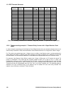
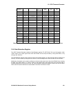
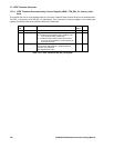
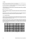
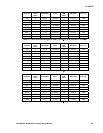
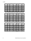
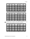
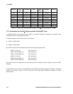
Table 17.1 below through to Table 17.11 on page 174 show the settings of the UART Division select and Baud
Rate Register to achieve given baud rates with various values of UART_CLK (BµILD_CLK) frequency. The
UART_CLK is based on values that can be produced by the PLL in the System Clock Generator, using the 40MHz
M_CLK from an RF front-end as the system clock reference. If any other value of UART_CLK frequency is used
(e.g. from a crystal via the Processor Crystal Oscillator), then the value of BRR and Reference Division selection
will need to be re-calculated.
Baud Rate
Required
Division
Select
Value
Reference
Clock (MHz)
Baud Rate
Ratio
Prog.
BRR
Value
Programmed
Baud Rate
Baud Rate
Error (%)
1200 8 2.5 129.20833 129 1201.923 -0.16
2400 4 5 129.20833 129 2403.846 -0.16
4800 2 10 129.20833 129 4807.692 -0.16
9600 1 20 129.20833 129 9615.385 -0.16
19200 1 20 64.104167 64 19230.77 -0.16
38400 1 20 31.552083 32 37878.79 1.357
57600 1 20 20.701389 21 56818.18 1.357
76800 1 20 15.276042 15 78125 -1.725
115200 1 20 9.8506944 10 113636.4 1.357
Table 17.1 UART baud-rate settings with UART_CLK (BµILD_CLK) frequency = 20MHz