


18: Watchdog Timer
GP4020 GPS Baseband Processor Design Manual 177
UART_CLK
PRIMARY
DOWN-COUNTER
32BIT
SECONDARY
DOWN-COUNTER
8BIT
DIV 16
=
WATCH_INT
RELOAD READ CONSTAT
=0
=0
CLR
START
WATCH_EN
START
[7:0]
BUILD BUS
INTERFACE
BUILD BUS
CLR
RESTART
KEY
0XECD9F7BD
WATCH_TM
TEST
[11:0]
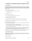
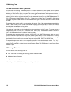
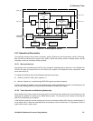
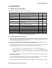
Figure 18.1 Watchdog Block Diagram
18.2 Operational Description
The watchdog consists of two counters; the primary, which is 32-bits long, and the secondary, which is 8-bits long.
Both counters are clocked off the system clock, UART_CLOCK; the primary counter is clocked directly, and the
secondary counter via a divide-by-sixteen pre-scaler.
18.2.1 Start-up behaviour
After system reset, the enable signal ’WATCH_EN’ controls the Watchdog start-up behaviour. In the GP4020, the
WATCH_EN signal is provided by bit 14 of the POW_CNTL register in the Peripheral Control Logic block, which
has a reset value of ‘0’.
To enable the Watchdog, either of the following techniques can be used:
• Set Bit 14 of the PCL POW_CNTL register to “1”;
• Write the “Restart key” to the Watchdog RESTART register (see below for details);
Once the watchdog is enabled, it cannot be disabled without resetting the GP4020. However, the watchdog can be
held off if the Watchdog RESTART key will need to be written to the RESTART register.
18.2.2 Timer Operation and Watchdog Restart Key
When enabled, the primary counter counts down from its 32-bit reload value towards zero. On reaching zero, the
Watchdog will generate an interrupt to the ARM7TDMI processor. The interrupt can be masked out by using the
MSK bit in the watchdog control register.
It then starts the secondary counter counting down to zero and sets the overflow (OVF) flag in the control register. If
the processor fails to restart the watchdog before the secondary counter reaches zero, it will generate a time-out
signal, which causes a system reset.