


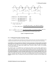


7: 12-Channel Correlator
GP4020 GPS Baseband Processor Design Manual 65
Address Offset Register Direction Function
0x1C0 to 0x1DC ALL Control
(see Table 7.3) (see Table 7.3)
0x1EC TIMEMARK_CONTROL Write Configure Raw Timemark output
0x1F0 TEST_CONTROL Write Set-up correlator test modes
0x1F4 MULTI_CHANNEL _SELECT Write Select channels for "MULTI"
0x1F8 SYSTEM_SETUP Write Set-up top-level correlator configs
0x1FC RESET_CONTROL Write Channel Reset (Disable)
0x200 to 0x20C Status Registers
(see Table 7.5) (see Table 7.5)
0x210 to 0x21C CH0 Accumulate
(see Table 7.4)
Correlator Channel Data Accumulation Registers
(see Table 7.4)
0x220 to 0x22C CH1 Accumulate
(see Table 7.4) (see Table 7.4)
0x230 to 0x23C CH2 Accumulate
(see Table 7.4) (see Table 7.4)
0x240 to 0x24C CH3 Accumulate
(see Table 7.4) (see Table 7.4)
0x260 to 0x26C CH5 Accumulate
(see Table 7.4) (see Table 7.4)
0x270 to 0x27C CH6 Accumulate
(see Table 7.4) (see Table 7.4)
0x280 to 0x28C CH7 Accumulate
(see Table 7.4) (see Table 7.4)
0x290 to 0x29C CH8 Accumulate
(see Table 7.4) (see Table 7.4)
0x2A0 to 0x2AC CH9 Accumulate
(see Table 7.4) (see Table 7.4)
0x2B0 to 0x2BC CH10 Accumulate
(see Table 7.4) (see Table 7.4)
0x2C0 to 0x2BC CH11 Accumulate
(see Table 7.4) (see Table 7.4)
0x2D0 to 0x2DC MULTI Accumulate
(see Table 7.4) (see Table 7.4)
0x2E0 to 0x2EC ALL Accumulate
(see Table 7.4) (see Table 7.4)
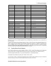
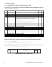
Table 7.2 12-channel correlator (CORR ) Register Map
Addresses for each of the Correlator Registers may be calculated from a base address with an increment for a
particular register.
In both the Accumulate and Control register sections in Table 7.2 above, there are some addresses labelled ALL or
MULTI in place of CHx. By writing to these addresses, either all the channels or a selection of channels set by
MULTI_CHANNEL_SELECT will be written to in one operation. This facility may be used to initialise the system
quickly or to load the next search settings with little bus use. This is a write only function and the corresponding
CHx read functions are not available at addresses labelled ALL or MULTI.
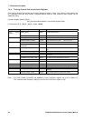
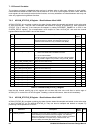
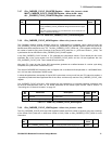
7.6.1 Tracking Channel Control Registers
Each Tracking channel has the Control registers as shown in Table 7.3 below. Each address has an independent
read and write function. Complete address offset for each Channel Control register can be determined using:
Correlator Register Address Offset = CHx_Control Base Address + Control Register Offset
For Example, CH3_CODE_DCO_INCR_LOW = 0x060 + 0x018 = 0x078
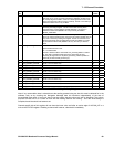
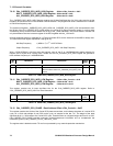
It can be seen in Table 7.3 below that the addresses for the Channel Control registers are used to Control the
channel in write mode, but give the channel Measurement Data when in read mode.