15: 1PPS Timemark Generator
154 GP4020 GPS Baseband Processor Design Manual
TOTAL max. oscillator drift error = (a) + (b).
In practice, the drift is much less than this under typical conditions ≈ 10 to 20ns
5. Computation induced error:
It is assumed that enough significant bits are retained such that this error approximates zero.
6. TIMEMARK transfer delay through drivers/cables:
This bias will be a significant contributor to the total delay figure, due to propagation from the 1PPS Timemark
generator through the chip to the output pin and along PCB track or cable to the receiving equipment. The
speed of electrical signals through a cable is generally less than speed of light, (approx. 0.25m / ns), but the
overall delay due to distance is probably quite small in itself; estimated 2ns.
The main delay will be due to getting the Timemark signal off-chip. With the GP4020 using a CLAOP01L1
output for Timemark, the delay through this port is approx. 11ns with a 10pF external load, and 19ns with a
50pF external load. There is also a residual random delay due to the Timemark output being re-clocked by the
M_CLK signal (25ns) when using the Timemark Delay Counter. The latter contributes 25ns/√12 = 7.2ns as a
standard deviation.
7. Propagation delays in the hardware:
These are biases that are estimated to be in the range of a few microseconds and are therefore the major
contributor to the TIMEMARK synchronisation error. An estimate could be included in the software to improve
total accuracy when the total hardware design is complete. Figures already documented within Section 7.4.11
"Signal Path Delay Introduced by Hardware Signal Processing" on page 61, suggest that the Hardware delay
in getting signals into and sampled by the 12-channel correlator will be in the order of 300ns. (Note that delays
after correlation do not affect the TIMEMARK synchronisation. This includes the delays in the accumulators.)
This figure excludes the dominant form of delay due to group-delay effects in filters and circuitry associated
with the RF Front-end components. The delay in the Murata SAFCC3542MC00Z SAW filter is of the order of
1200ns and the delays in the other IF filters probably add up to around 500ns giving a total contribution to the
bias of around 1700ns.
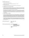
TOTAL Typical Estimated Bias ≈ 15ns + 300ns + 1700ns
≈ 2015ns.
TOTAL Typical Estimated Random Error ≈ RMS of (Time Transfer Error
+ Clock Resolution
+ Oscillator Drift Residual Error
+ Computation induced Error)
≈ √(20
2
+ 7
2
+ 10
2
+ 0 + 7
2
)
ns.
≈ 25ns.


