


7: 12-Channel Correlator
80 GP4020 GPS Baseband Processor Design Manual
Bit
No.
Mnemonic Description Reset
Value
R/W
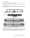
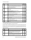
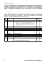
15 GPS_NGLON Select mode of C/A code generator.
'0' = Run C/A code generator in GLONASS mode, to generate the fixed 511-bit
sequence used by all GLONASS Satellites. After a reset, GPS mode is
selected, but with all zeros in the G2 generator, the G1 code is seen at the
output of the C/A code generator.
'1' = Run C/A code Generator in GPS mode
1W
14:13 TRACK_SEL
[1:0]
Select code of Tracking arm output.
'00' = Early Code
'01' = Late Code
'10' = Dithering code (alternate Early Code and Late Code).
'11' = Early-minus-late Code
00 W
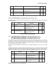
12 PRESET/
UPDATEB
Selects either PRESET or UPDATE mode.
'0' = select UPDATE mode. Data updates occur at each data DUMP.
'1' = PRESET mode. Data updates occur at each TIC.
This bit is cleared to Low after the Preset function has been done, that is after the
first TIC following the loading of the Epoch counters.
0W
11 CODEOFF/
ONB
Test mode facility to disable the C/A Code Generator.
'0' = C/A code generator Enabled.
'1' = C/A code generator disabled; the Prompt, Early and Late codes are held
High (code mixer outputs exactly follow inputs) and the Early–minus–late
code is held LOW.
0W
10 SOURCESEL Selects which input source to be used by the channel, for test purposes only
(
MAG1 and SIGN1 are NOT separately bonded out on 100pin GP4020 device).
'0' = selects SIGN0 and MAG0 inputs.
'1' = selects SIGN1 and MAG1 inputs, via GPIO[0] (pin 100) and GPIO[1] (pin
99), when GP4020 UIM_TEST mode enabled.
0W
9:0 G2_LOAD [9:0]
C/A CODE SELECTION FUNCTION. G2 register start pattern. See
Table 7.28
for data detail.
0x000 W
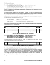
Table 7.29 CORR CHx_SATCNTL Register
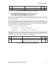
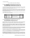
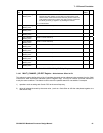
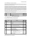
7.6.24 MEAS_STATUS_A Register - Read Address Offset 0x204
This register indicates if measurement data generated by any of the 12 correlator channels, which has been
generated more than once since the previous read of the register, has not been read, and has hence been missed.
If this register is always read after the Code Phase Counter, it indicates whether measurement data has been
missed before the last read of the Code Phase Counter. All CHx_MISSED_MEAS_DATA bits are set Low by a
hardware or software reset.
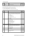
Bit
No.
Mnemonic Description
Reset
Value
R/W
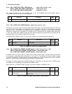
15:14
Not Used
'0' when read - R
13 TIC Set HIGH at every occurrence of TIC and is cleared by reading this
ACCUM_STATUS_B register. This bit can be used as a flag to the
microprocessor, to time software module swapping. It is reset by a
hardware master reset (NRESET ='0') but not by an MRB in
RESET_CONTROL.
0R
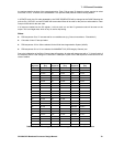
12 MEAS_INT Provided that interrupts are enabled, the MEAS_INT bit is set High at each
TIC and 50 ms before each TIC (if the TIC period is greater then 50 ms),
and is cleared by reading this register. This bit can be used to tell the
microprocessor that new Measurement Data is available. It is reset by a
hardware master reset (NRESET = '0'), but not by a software reset.
0R