


12: Peripheral Control Logic
GP4020 GPS Baseband Processor Design Manual 115
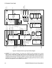
• WATCH_TM (or Watchdog Time-out) signal. This is an internally generated Reset signal comes from the on-
chip Watchdog module. This will occur if the Watchdog has interrupted the Firefly MF1, but an interrupt service-
routine in software has failed to reset the Watchdog. The Watchdog is reset by sending a 32-bit reset key within
approx. 200µs (refer to Section 18 "WATCHDOG TIMER (WDOG)" on page 176, for more information). A
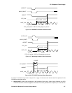
system reset will occur as shown in Figure 12.7 on page 117. The WATCH_TM reset source will reset all
registers which NSRESET will reset, except for PER_STAT [4:0] register bits, which are only reset by an
NSRESET event.
• A software Reset signal, SFT_RESET, can be set to initiate a reset of the Firefly MF1 and the 12-channel
correlator by writing a '0' to bit 4 of the PER_STAT register. The SFT_RESET will then cycle low for one
UART_CLK cycle. This could be activated in conjunction with a software interrupt service routine and the
RF_PLL_LOCK interrupt signal into the INTC block, but could also undertake a reset in some other software
circumstances. The reset occurs as shown in Figure 12.8 on page 117. The reset state for this signal is '0' for a
read and '1' for a write.
WATCH_TM
RF_PLL_LOCK
RTC_CLK
NSRESET
1
POWER_GOOD
EN_POW_RST
1
SFT_RESET
UART_CLK
NRESET
NPOR_RESET
D Q
D Q
EN_PLL_RST
D Q
D Q
1
PLL_IN_SEL[1:0]
LATCH
=
3 BIT UP-
COUNTER
PLL_PD
=7
PLL_ENABLE
PLL_SLEEP
1
PLL_RESET
POW_RESET
NSRST_RESET
WAT_RESET
MULTI_FNIO
D Q
EXT_NCS0
NPOR_
RESET
2 BIT UP-
COUNTER
=3
INT_NCS0
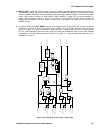
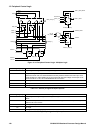
Figure 12.2 Peripheral Control Logic - Reset Logic