


14: System Clock Generator
142 GP4020 GPS Baseband Processor Design Manual
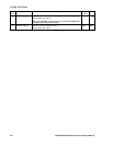
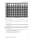
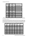
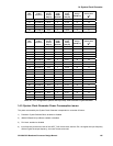
If you intend to change the frequency of the PLL on the fly during time-critical code-execution, care should be used
to ensure that the PLL is allowed to stabilise before allowing the code execution to continue. It is recommended that
the software waits for the period specified by the “Worst-case settling time” parameter in Table 14.2 on page 142,
Table 14.3 on page 143 and Table 14.4 on page 144 after the new frequency has been programmed in. This will
allow the PLL to lock to the new frequency required and reduce time-related jitter to a minimum.
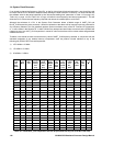
Although the existence of a PLL in the System Clock Generator allows a flexible range of UART_CLK and
BµILD_CLK frequencies to be produced, it should be pointed out that there will be harmonic spurious produced for
any frequency selected. This can potentially produce spurious radiation at any of the RF Front-end IF frequencies,
or, in some cases in the Receive RF L1 band. Whilst every attempt has been made to ensure that the GP4020 will
respond at many key UART_CLK frequencies, it cannot be ruled out that there will be values where self-generated
interference occurs.
Therefore, care should be used to ensure that any value of UART_CLK frequency selected, in conjunction with the
wait-state properties of any external memory components, does not produce in-band radiation at any of the
following key GP2015 RF Front-end frequencies:
1) 1575.42MHz ± 2.0MHz
2) 175.42MHz ± 2.0MHz
3) 35.42MHz ± 2.0MHz
UART
_CLK
O/P
Freq.
(MHz)
I/P
Freq.
MHz
PLL
Mult
Fact
Prog.
Divider
setting
DIV
[4:0]
Charge
Pump
setting
CHP
[4:0]
PLL
SYNC
MODE
SYN
CEN
PLL
O/P
VCO
Freq.
MHz
VCO
Freq.
Range
VCOD
[1:0]
BY-
PASS
PLL
PLL_
BYP
PLL
O/P
Divide
Factor
B_
CLK
_SEL
[1:0]
Ts
3
(µs)
1.25 10.0
1
N/A N/A N/A N/A N/A N/A 1 8 11 N/A
2.5 10.0
1
N/A N/A N/A N/A N/A N/A 1 4 10 N/A
3.75 10.0
1
3 00001 01000 0 30 10 0 8 11 47
5.0 10.0
1
N/A N/A N/A N/A N/A N/A 1 2 01 N/A
6.25 10.0
1
5 00011 00111 0 50 01 0 8 11 52
7.5 10.0
1
3 00001 01000 0 30 10 0 4 10 47
8.75 10.0
1
7 00101 01001 0 70 01 0 8 11 44
10.0 10.0
1
N/A N/A N/A N/A N/A N/A 1 1 00 N/A
11.25 10.0
1
9 00111 00110 0 90 00 0 8 11 58
12.5 10.0
1
5 00011 00111 0 50 01 0 4 10 52
13.75 10.0
1
11 01001 00111 0 110 00 0 8 11 52
15.0 10.0
1
3 00001 01000 0 30 10 0 2 01 47
16.25 10.0
1
13 01011 01001 0 130 00 0 8 11 44
17.5 10.0
1
7 00101 01001 0 70 01 0 4 10 44
18.75 10.0
1
15 01101 01010 0 150 00 0 8 11 41
20.0 20.0
2
N/A N/A N/A N/A N/A N/A 1 1 00 N/A
21.25 10.0
1
17 01111 01011 0 170 00 0 8 11 38
22.5 10.0
1
9 00111 00110 0 90 00 0 4 10 58
23.75 10.0
1
19 10001 01101 0 190 00 0 8 11 35
25.0 10.0
1
5 00011 00111 0 50 01 0 2 01 52
26.25 10.0
1
21 10011 01110 0 210 00 0 8 11 33
27.5 10.0
1
11 01001 00111 0 110 00 0 4 10 52
28.75 10.0
1
23 10101 01111 0 230 00 0 8 11 32
30.0
4
10.0
1
6 00100 01000 0 60 01 0 2 01 47
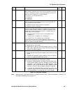
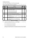
Table 14.2 Valid UART_CLK frequencies that can be produced from M_CLK (from RF Front end)