


18: Watchdog Timer
178 GP4020 GPS Baseband Processor Design Manual
To restart the watchdog counter, a specific 32-bit value (=0xECD9F7BD; the RESTART key) must be programmed
into the watchdog restart register. This 32-bit “key” activates the restart mechanism, which performs the following
actions:
1) Loads the watchdog primary counter from the reload register
2) Resets the OVF (overflow) flag in the control register
3) Restarts the primary counter
4) Reloads and disables the secondary time-out counter
5) Removes the time-out signal
The reload register enables the interrupt period to be varied in software. Changes to the reload register value will
only be reflected in the main watchdog counter after the next software reload.
18.2.3 Watchdog Timer ranges
The input clock to the Watchdog is UART_CLK, which is essentially the Firefly System Clock. Typically, the default
UART_CLK frequency is 20MHz, unless the System Clock Generator sets this to another value.
The Watchdog Primary Counter, used to define the Watchdog Interrupt period, has a 32-bit range, and hence has a
maximum value of 2
32
~= 4295million. With a 20MHz clock this gives a maximum interrupt period of:
4295000000 / 20000000 = 215 seconds
The Watchdog Secondary counter, used to define the Watchdog Time-out period, has an 8-bit range, and hence
has a maximum value of 2
8
= 256. The clock into the Secondary counter is the UART_CLK input divided by 16,
which gives an effective clock of 1.25MHz when UART_CLK is 20MHz. With UART_CLK = 20MHz, the maximum
Watchdog Time-out period is:
256 / 1250000 = 204.8µs.
In a GPS system using the GP4020, it is recommended that the Interrupt service routine which is generated in
software allows for the fact that the Watchdog Interrupt should be serviced quickly, in order to avoid a complete
chip reset.
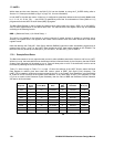
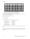
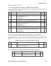
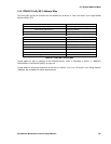
18.3 Watchdog Register Map
The GP4020 Watchdog base address is 0xE0004000.
The addresses in the Register Map are specified as offsets from the Watchdog base address.
Address Offset Register Direction Function
0x000 CONSTAT Read/Write Control and status bits + Secondary Counter
Start Value (Time-out period).
0x004 RELOAD Read/Write Primary Counter Start Value (interrupt
frequency).
0x008 READ Read Read current Primary Counter Value.
Only accessible in TEST mode.
0x00C RESTART Write Restart “key” input. Key value = 0xECD9F7BD.
0x010 TEST Read/Write
Access test signals + Read current Secondary
Counter Value. Only accessible in TEST mode.
0x014.....0xFFF
Reserved
Table 18.1 Watchdog Register Map
TEST mode can be activated only by setting GP4020 ‘TEST’ input (pin 67 (100-pin package)) to Logic ‘1’, and
‘TESTMODE’ (pin 74 (100-pin package)) is set to Logic ‘0’.