


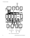
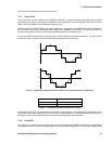
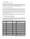
7: 12-Channel Correlator
GP4020 GPS Baseband Processor Design Manual 57
the received signals therefore, a locally generated code must be chosen to precisely match the spreading code
type, rate, and phase.
This pattern is then multiplied bit-by-bit with the incoming data stream and the results integrated over the code
length to recover the signal.
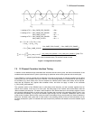
The process of signal acquisition is simply the matching of receiver settings to the actual signal values. To make
matters more complicated the satellite carrier frequency is shifted a little by the Doppler effect due to the motion of
the satellite. The user clock will drift randomly, and (in most situations) the signal-to-noise-ratio (SNR) is poor for
some satellites. Therefore, the software must be 'wide-band' to find the signal and 'narrow-band' to reduce noise,
leading to very different programs in different applications. For all tracking channels, the signal processing software
needs the following sequence of activities:
1. Program CHx_SATCNTL register to select the desired GPS Gold code (PRN number) for the selected
satellite and also select the code type for the mode of the correlator tracking arm. It is often best when in
acquisition mode to fix the tracking arm to Dithering Mode (alternate 'Early' and 'Late') and do a search in two
phases at once. Then switch the tracking arm to a tracking mode once a satellite is found.
2. Program CHx_CARRIER_DCO_INCR_HIGH and CHx_CARRIER_DCO_INCR_LOW registers. The values
programmed into these two registers are concatenated and are used to set the local oscillator frequency for the
digital mixing performed in the 12-channel correlator. This brings the incoming 2-bit digitised signal from the RF
Front-end down to baseband. The value to be programmed is equal to the nominal local oscillator frequency
plus the estimated Doppler shift compensation plus the estimated user clock frequency drift compensation.
3. Program CHx_CODE_INCR_LO and CHx_CODE_INCR_HI. The value to be programmed in these registers
represents twice the nominal chipping rate of the C/A code (2.046 MHz); in addition, if desired, a small
compensation for the Doppler shift and user clock frequency drift.
4. Release the tracking channel reset by programming the RESET_CONTROL register with the proper value.
This will cause the correlation process to start.
5. Obtain accumulated data from Accumulated Data Register readings. Several consecutive readings on the
same tracking channel can be added to increase, at will, the integration period of the correlation.
6. Decide if the GPS signal has been found by comparing the correlation result with a threshold. If found then
jump to a signal pull-in algorithm. Note that both in-phase and phase quadrature accumulated data have to be
considered since at this time, the carrier DCO local oscillator phase is not necessarily in phase with the
incoming GPS signal.
7. If the GPS signal has not been found, a new trial has to be made with different carrier DCO, code DCO, or
gold code phase programming. Typically, both DCOs would be held constant while the Gold code phase is
varied to try all of the 2046 half chip positions possible. The carrier DCO would then be programmed with
slightly different values and the Gold code phase positions would again be scanned. The Gold code phase is
varied by programming the CHx_CODE_SLEW register and can be varied by increments of half a code chip.
8. Once the GPS signal has been found, the code phase alignment, the carrier phase alignment and the
Doppler and user clock bias compensations are still coarse. The code phase alignment is only within a half
code chip, the carrier DCO is not in phase with the incoming signal and infrequency is still in error by up to the
increment used for successive trials.
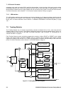
The signal processing software must next use a pull-in algorithm to refine these alignments. There are many
suitable types of algorithm to choose from, such as:
i) successive small steps until the error is too small to matter, like an analogue PLL;
ii) using more complicated signal processing to estimate the errors and jump to a much better set of values.
The signal pull-in algorithm will then program CHx_CARR_INCR_LO / HI registers with more values that are
accurate for the Carrier DCO. Corrections to the Gold code phase smaller than a half chip cannot be done by
programming CHx_CODE_SLEW registers in the Code Generator. This can be done by setting the