


10: Interrupt Controller
GP4020 GPS Baseband Processor Design Manual 107
10 INTERRUPT CONTROLLER (INTC)
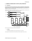
The Interrupt Controller can manage upto 32 Interrupt sources. In the GP4020, 18 interrupt sources are present: 16
internal sources, and 2 external sources. The Interrupt controller processes these raw interrupt sources down into
two main CPU interrupts. These are called FIQ and IRQ. The names come from the two prioritised interrupts on the
ARM family of processors. The FIQ stands for “Fast Interrupt Request”, whereas IRQ is a regular interrupt request.
The differences between the two interrupt types are as follows:
1) FIQ interrupts have higher priority than IRQ interrupts. As such, an IRQ interrupt can be interrupted by an FIQ
interrupt. However, an FIQ interrupt may not be interrupted by another interrupt. Also note that an IRQ interrupt
cannot be interrupted by another IRQ interrupt.
2) There are “private” banked registers for use when the processor is in either FIQ or IRQ modes. In IRQ mode,
there are two such registers. In FIQ mode, there are seven banked registers for the programmer’s use. This
larger number of banked registers means that latency-sensitive interrupts can be processed without the
overhead of having to save the context of the machine by stacking registers before use.
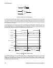
The Interrupt Controller is designed to work with the BµILD bus, and its control is via a series of registers from that
bus. It can basically be considered as two large OR gates with a certain amount of pre-processing carried out on
each channel before they are ORed together. Each interrupt channel has a hierarchical priority in terms of IRQ:
Channel 0 has highest priority and channel 31 the lowest. FIQ has ultimate priority over all IRQ.
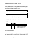
ADDRESS EXCEPTION
0x00000000 Reset
0x00000004 Undefined Instruction
0x00000008 Software Interrupt
0x0000000C Abort (prefetch)
0x00000010 Abort (data)
0x00000014 Reserved
0x00000018 IRQ
0x0000001C FIQ
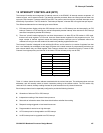
Table 10.1 Interrupt Vector Summary
Table 10.1 above shows the vector address associated with the various interrupts. The addresses shown are byte
addresses, and will normally contain a branch instruction pointing to the relevant routine. The FIQ routine may
reside at 0x1C onwards, thereby avoiding the need for (and execution time of) a branch instruction.
Each Interrupt channel can be separately configured to provide the following functions:
• Generation of either an FIQ or IRQ interrupt
• Independent masking of the channel interrupt source
• Status bits to indicate the state of the channel both before and after the masking
• Responds to edge-triggered or level-sensitive sources
• Programmable for active low or high interrupts
• A FIQ interrupt can be downgraded to an IRQ interrupt
• An IRQ interrupt can be upgraded to an FIQ interrupt