


12: Peripheral Control Logic
GP4020 GPS Baseband Processor Design Manual 113
12 PERIPHERAL CONTROL LOGIC (PCL)
12.1 Introduction
The Peripheral Control Logic (PCL) is used to control GP4020 chip-wide functions. The PCL can be considered to
have the following discrete functions:
1) Chip Reset logic
2) PLL Enable logic
3) Multiplex logic
4) Interrupt and wake-up logic
5) Chip status monitoring.
6) Chip-wide power-control
7) Test mode set-up
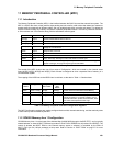
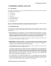
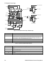
Figure 12.1 below shows a block diagram of most of the functions that the PCL performs. Note that Chip-wide
power-control and Test-mode set-up have not been explicitly indicated in the diagram.
12.2 Chip Reset Logic
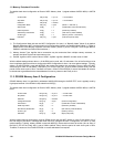
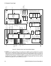
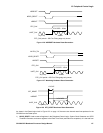
The GP4020 uses a number of sources to allow chip-wide resetting of clocks and registers. Figure 12.2 on page
115 shows the logic contained within the Reset Logic Block of the PCL. The main sources for reset come from the
following signals:
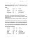
• RF_PLL_LOCK (Pin 56 (100-pin package)) – when Low, this indicates that the RF Front-end PLL is not locked.
Therefore the clocks to & from the RF Front-end (CLK_T (Pin 58), CLK_I (Pin 59), SAMPCLK (Pin 63)), and the
digitised IF on the SIGN0 and MAG0 inputs (pins 61 and 62), are NOT valid. A reset of the Firefly MF1 and the
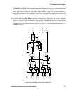
12-channel correlator will occur as shown in Figure 12.3 on page 116, if RF_PLL_LOCK is taken Low (i.e. '0'). In
addition, this line feeds the Interrupt Controller (INTC), which can respond to this if configured to do so.
The RF_PLL_LOCK input can be inhibited from resetting the Firefly and Correlator by ensuring that the
EN_PLL_RST bit of the “PER_STAT” register is set to “0”.
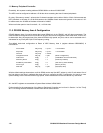
• POWER_GOOD (Pin 64 (100-pin package)) – when Low, this indicates that the voltage supply to the GPS
receiver is below a limit defined by a Power-on reset reference comparator on the RF Front-end. A reset of the
Firefly MF1 and the 12-channel correlator will occur as shown in Figure 12.4 on page 116. In this diagram, it is
assumed that a clock is present throughout the POWER_GOOD event.
The POWER_GOOD input can be inhibited from resetting the Firefly and Correlator by ensuring that the
EN_POW_RST bit of the “PER_STAT” register is set to “0”.
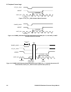
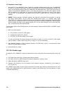
In a GPS receiver using the GP2010 or GP2015 RF Front-end, a POWER_GOOD event normally signifies the
loss of power to the RF Front-end also. This results in RF_PLL_LOCK being set Low, and the disappearance of
CLK_T and CLK_I clock signals. When Power is re-applied, the POWER_GOOD line will be set High quickly
after power-up. However, if a GP2010 or GP2015 RF Front-end is used, the PLL in the RF chip will typically
take 5ms from power-up to set RF_PLL_LOCK to High. This is shown in Figure 12.5 POWER_GOOD
Hardware Reset Generation when POWG_EN = '1'. Assumes that power to RF Front-end fails, and
RF_PLL_LOCK is low for upto 5ms after power-up. on page 116.
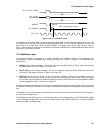
Also, if POWG_EN (bit 15 in the POW_CNTL register) is set to '1', the POWER_GOOD line will also power
down the whole GP4020 chip, except for the Real Time Clock and Data Retention register. A reset of the Firefly
MF1 and the 12-channel correlator will occur, along with a power-down of most GP4020 functions. Refer to
Section 12.6 "Chip-wide Power Control modes" on page 123, for more information.