


17: UARTs
174 GP4020 GPS Baseband Processor Design Manual
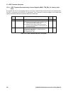
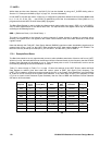
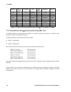
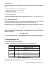
Baud Rate
Required
Division
Select
Value
Reference
Clock (MHz)
Baud Rate
Ratio
Prog.
BRR
Value
Programmed
Baud Rate
Baud Rate
Error (%)
1200 8 4.375 226.86458 227 1199.287 0.059
2400 4 8.75 226.86458 227 2398.575 0.059
4800 2 17.5 226.86458 227 4797.149 0.059
9600 1 35 226.86458 227 9594.298 0.059
19200 1 35 112.93229 113 19188.6 0.059
38400 1 35 55.966146 56 38377.19 0.059
57600 1 35 36.977431 37 57565.79 0.059
76800 1 35 27.483073 27 78125 -1.725
115200 1 35 17.988715 18 115131.6 0.059
Table 17.11 UART baud-rate settings with UART_CLK (BµILD_CLK) frequency = 35MHz
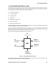
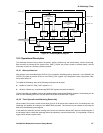
17.3 Connections to the BµILD bus and the Firefly MF1 Core
The GP4020 UARTs are configured such that UART1 is a standard Firefly MF1 component, and UART2 is also
connected to Firefly via the external BµILD bus.
The Base Addresses of the GP4020 UARTs are as follows:
• UART1 = 0xE001 8000,
• UART2 = 0xE001 9000.
Each UART produces three interrupt lines to the Firefly Interrupt Controller (INTC):
UART1 Tx / Rx error - INTC channel 14
UART1 Receive Buffer Full - INTC channel 15
UART1 Transmit Buffer Full - INTC channel 16
UART2 Tx / Rx error - INTC channel 26
UART2 Receive Buffer Full - INTC channel 27
UART2 Transmit Buffer Full - INTC channel 28
Since INTC channel 0 has highest priority, this means that UART1 interrupts will have a higher priority than UART2
interrupts.
Further details of the function and programming of the GP4020 Universal Asynchronous Receiver Transmitter
(UART) can be found in Section 4 of the "Firefly MF1 Core Design Manual" DM5003, available from Zarlink
Semiconductor.