


14: System Clock Generator
GP4020 GPS Baseband Processor Design Manual 137
14.3 Processor Crystal Oscillator
The Processor Crystal Oscillator may need to be used with an external crystal, to generate the clock source for the
UART_CLK signal. The two instances where this may be necessary are:
1) If the RF Front-end is to be used in a Power-down or sleep mode; powering down the RF Front-end will disable
the 40MHz from the RF Front-end and also disable the 40MHz Low level Differential block, leaving the GP4020
potentially locked up without any system clock;
2) To produce a system clock at a strategic frequency that cannot be derived from the PLL using the input clock
reference from the M_CLK source (10.0MHz or 20.0MHz).
The Processor Crystal Oscillator is switched in by default when TEST (pin 67 (100-pin package)) is set High. This is
for test purposes only.
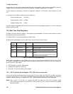
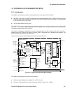
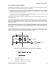
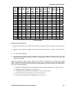
The Processor Crystal Oscillator will operate with Crystals over the frequency range of 10.0MHz to 16.0MHz. It is
based on a Pierce Oscillator Cell, as shown in Figure 14.3 below. Output from the cell is via a buffered Schmitt
trigger, which provides a square wave, which is compatible with the internal clock requirements of the GP4020,
including the PLL block.
Once a crystal has been chosen in the range 10.0 to 16.0MHz, the load capacitors C1 and C2 can be selected. The
capacitor values ensure correct operation of the pierce oscillator such that the total loop gain is greater than unity.
Correct selection of the two capacitors is very important and the following method is recommended to obtain values
for C1 and C2.
Although oscillation may still occur if the loop gain is just above 1, a loop gain of 5 is recommended. This is to
ensure that oscillations will occur across all variations of temperature, voltage supply and silicon process batch. In
addition, this ensures that the circuit will exhibit a reliable start-up performance.
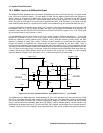
Crystal
10.0 - 16.0MHz
PR_XIN
PR_XOUT
PRX_PDOWN
220k
ENBO
C1
C2
OSCOUT
Figure 14.3 Processor Clock Oscillator, crystal connection configuration
()
1
t
11
−
++
+
=
outininf
inout
in
mou
ZZCR
CC
C
gC
A
............ 1
()
ESRfC
Z
out
in
×
=
2
2
1
π
....................................... 2
where: A = Total Loop Gain (goal = 5)
C
in
= Capacitance on PRX_IN pin = (C1 + 10pF)
C
out
= Capacitance on PRX_OUT pin = (C2 + 10pF)