


Index - IV GP4020 GPS Baseband Processor Design Manual
Figure 12.10 Peripheral Control Logic - Multiplex Logic ....................................................................................120
Figure 12.11 Peripheral Control Logic - Peripheral Interrupt and Wake-up control logic..................................... 121
Figure 13.1 Real Time Clock Block Diagram.................................................................................................... 131
Figure 14.1 System Clock Generator Block Diagram........................................................................................135
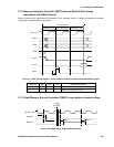
Figure 14.2 Circuit to interface OPCLK+/- from GP2015 to CLK_T / _I on GP4020............................................136
Figure 14.3 Processor Clock Oscillator, crystal connection configuration...........................................................137
Figure 14.4 Connections of a TCXO frequency reference to the GP4020 Processor Crystal Oscillator...............139
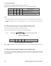
Figure 14.5 GP4020 System Clock Generator PLL Configuration .....................................................................140
Figure 14.6 PLL Programmable Divider Configuration......................................................................................140
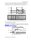
Figure 15.1 1PPS Timemark Generator, with interface to 12-channel correlator block .......................................150
Figure 15.2 Timemark output using ARM_TIMEMARK signal, triggered from software. ..................................... 151
Figure 15.3 Typical timing relationship between UTC, TIC and Timemark, for small Timemark Delay values......152
Figure 16.1 Up-Integration Module interfaces...................................................................................................167
Figure 18.1 Watchdog Block Diagram..............................................................................................................177
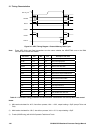
Figure 21.1 MPC Timing Diagram - External Memory Write Cycle .................................................................... 193
Figure 21.2 MPC Timing Diagram - External Memory Read Cycle.................................................................... 194
Figure 21.3 MPC Timing Diagram - External Memory Read Cycle with external Wait-State control.................... 195
Figure 21.4 DMAC timing: Single address transfer........................................................................................... 195
Figure 21.5 Interrupt timing ............................................................................................................................. 196
Figure 21.6 External Broadcast diagnostic signal (SBDIAG) timings from SSM. ................................................197
Figure 21.7 JTAG Interface Characteristics......................................................................................................197