


8: DMA Controller
GP4020 GPS Baseband Processor Design Manual 99
2.1.12) Clear to "0" the Peripheral Location bit (bit 18), to indicate that the data buffer for a dual-addressed
transfer is internal to the DMAC.
2.2) Set DMAC Packet Size (bits [7:0]) of the Packet Size Register (PSR) to zero (i.e. 0x00). This signifies that
each DMAC data packet will be one word in size.
2.3) Set the DMAC Base Address Register (BAR) for DMAC Channel 1 with the base memory-location of the
where the data to be copied exists (e.g. EPROM). Also, set the same register for DMAC Channel 2 with
the base memory location of where the copied data needs to be written to (e.g. SRAM or FLASH). With
the Address Mode set to “dynamic”, this base-address should be an area of the memory map where there
is a contiguous memory space.
2.4) Set the DMAC Base Transfer Count Register (BTR) of the DMAC Read channel (channel 1), to indicate to
the DMAC how many transfers are required in the data transfer operation being programmed. In the case
of the Packet transfer being defined here, this number is the (number of data bytes - 1), of Packet size "1"
which are required to be transferred between the two memory locations previously defined. So if the
transfer is to be for 10,000 8-bit bytes, the setting for this register should be "10,000 - 1" = "9,999" =
0x270F.
3) Once all the DMAC features have been programmed:-
3.1) Set to “1” the DMAC Channel Status bit (bit 0) in both the Channel 1 and 2 Control and Status Register
(CSR), to allow the DMA transfer to be triggered as defined in step 2) above. This action should be done
independently of any other settings to the Control and Status Register in order to avoid setting and
triggering errors.
Note: A write of a bit to the DMAC CSR register involves writing a byte, half-word or word. It is worth ensuring
that the settings already programmed into the CSR are not corrupted when setting bit 0 to "1", by re-
writing the values of all the other bits in the register to those defined above.
Refer to Section 8.3 below on DMAC Triggering to get an indication of how both Software and Hardware triggering
operates with a DMA transfer.
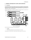
8.3 DMAC Triggering
8.3.1 Hardware Triggering
Hardware Triggering of a DMAC channel is the normal mode used in Single-addressed (Fly-by) data transfers.
The configuration of the DMAC Hardware Triggering for DMAC Channel 1 occurs by setting bits [5:3] of the System
Configuration Register (SCR) in the System Services Module (SSM) to any of the values in Table 8.1 on page 92. A
packet of data, as defined within the DMAC Packet Size Register (PSR), will be transferred every time a Hardware
Trigger is received. This could be when any of the interrupt events in Table 8.1 on page 92 occurs.
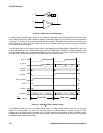
For UART Transmit Triggers, this occurs when the UART Transmit Buffer is empty and waiting for more data.
For UART Receive Triggers, this occurs when the UART Receive Buffer is full and waiting for data to be read.
Transfers will continue on each Hardware Trigger event until the amount of data packets defined by the DMAC
Base Transfer Count Register (BTR) have been transferred. The length of hardware trigger will determine how
many triggers are needed to transfer the BTR Count. In the case of the UART, a new Hardware trigger will be
produced for every packet of data transferred.
DMAC Channel 2 can only be hardware triggered from UART2, and no other source. The DMAC trigger is actually
configured by the type of interrupt set-up in the UART 2 either on Transmit Buffer Empty, or Receive Buffer Full.