


8: DMA Controller
GP4020 GPS Baseband Processor Design Manual 97
this number is the (number of data bytes - 1), of Packet size "1" which are required to be transferred from
memory to the UART 1 or 2 transmit port. So if the transfer is to be for 10,000 8-bit bytes, the setting
for this register should be "10,000 - 1" = "9,999" = 0x270F.
3) Once all the DMAC features have been programmed:-
4.1) Set to ”1” the Receive Interrupt Enable bit (bit 4) of the UART 1 (or 2) Serial Control Register (CR) to
enable interrupts generated when the UART Transmit register is empty. This is vital when using UART2
with hardware DMAC triggers from UART2, to ensure that the DMAC is triggered correctly (refer to
Section 8.3 "DMAC Triggering" on page 99).
4.2) Set to “1” the DMAC Channel Status bit (bit 0) in the Channel 1 (or 2) Control and Status Register (CSR),
to allow the DMA transfer to be triggered as defined in step 2) above. This action should be done
independently of any other settings to the Control and Status Register in order to avoid setting and
triggering errors.
Note: A write of a bit to the DMAC CSR register involves writing a byte, half-word or word. It is worth ensuring
that the settings already programmed into the CSR are not corrupted when setting bit 0 to "1", by re-
writing the values of all the other bits in the register to those defined above.
Refer to Section 8.3 "DMAC Triggering" on page 99 for information of how both Software and Hardware triggering
operates with a DMA transfer.
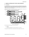
8.2 Dual-Addressed (Buffered) Data Transfers
Dual Addressed (Buffered) data transfers are possible between any two memory locations within the GP4020.
The DMAC can use both of its channels to undertake a Dual-addressed transfer from one memory location to
another memory location. A Dual-addressed transfer does not use the Hardware controls used with the UART
peripherals, and so any two memory-mapped components within the GP4020 can use the DMAC Dual Addressed
Data Transfer.
The higher priority channel (DMAC Channel 1) is used as the “Read” channel, and the lower priority channel of the
pair (DMAC Channel 2) becomes the Write channel.
Each Dual-Addressed Data Transfer requires two bus transactions: the first to read the data from the source to a 1-
word deep buffer, and the second to write the data to the destination. Refer to Section 6.2.2 in the Firefly MF1 Core
Design Manual (DM5003) for details of Dual-addressed transfers.
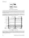
8.2.1 Set up example of DMAC for a Dual-Addressed transfer between two memory locations.
The following text shows an example of the sequence of events required to program and enable the GP4020
DMAC to provide a Dual-Addressed Data transfer between two contiguous areas of memory. A Dual-addressed
transfer uses both DMAC channels simultaneously, one to read from one location into a "buffer", and the other to
write to another location.
1) Set-up the source of DMAC Triggering (i.e. the prompt that initiates the DMA transfers following the DMAC
program cycle). The GP4020 DMAC can take triggers from both software and Hardware sources.
1.1) If software triggering is required (and not hardware triggering), this can be programmed explicitly into the
DMAC (refer to Section 8.3 "DMAC Triggering" on page 99).
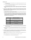
1.2) If hardware triggering is required, the trigger source can be selected by setting up the DMAC Trigger
Source bits within the System Configuration Register (SCR) (Address 0xE000 2004) in the System
Services Module (SSM). Refer to Table 8.1 Hardware Trigger Source selection for DMAC Channel 192.
Note that Hardware triggering is not normally appropriate for Dual Addressed Transfers.