


13: Real Time Clock
GP4020 GPS Baseband Processor Design Manual 131
13 REAL TIME CLOCK (RTC)
13.1 Introduction
The Real Time Clock (RTC) is used to provide an incremental time indicator. It is based on a 32768Hz watch-
crystal oscillator, with a 15-bit divider to produce a 1Hz clock, and a 24-bit counter accumulator to count seconds
from zero upto a maximum of 194days (approx. 6 months). The RTC operates on the principle of incremental
elapsed seconds, rather than absolute time. Consequently, the RTC does NOT store dates on the Gregorian
Calendar, and is hence immune from the Year 2000 rollover issue.
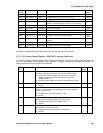
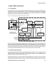
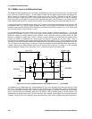
Figure 13.1 below shows a block diagram of the Real Time Clock.
32.768kHz
OSCILLATOR
RTC_PRE
(Prescaler re-timed to
processor clock)
UIM BUS
32768Hz
1Hz
RTC_SEC_T[7:0]
8 MSBs of second Counter
latched during RTC_PRE /
RTC_SEC read
RTC_SEC
(Second counter re-timed to
processor clock)
RTC_
XIN
RTC_
XOUT
C1 = 10pF
C2 = 10pF
10Mohm
RTC_PRE[15:1]
32768Hz
Crystal
EXTERNAL
COMPONENTS
RTC_CLK
(TO PCL)
15 bit
Divide by 32768
Pre-scaler
RTC_
RESB
24 bit Counter for
RTC Seconds
COMPARATOR
RTC_CMP_INT
(TO PCL)
COMP_RTCP[15:1]
15 bit Pre-scaler
Comparison Register
COMP_RTCS[7:0]
8 bit RTC Second
Comparison Register
RTC_SEC_B[15:0]
RESET
RTC_PRE [15:1]
NPOR_RESET
(FROM PCL)
RTC_SEC_B[7:0]
UIM ADDRESS & DATA BUS
RTC_CMP_INT goes HIGH
when Pre-scaler value and
8 LSBs of RTC Second Counter
match Comparison Register values
Figure 13.1 Real Time Clock Block Diagram
The RTC incorporates some comparison registers (with a comparator), which allow an interrupt signal to be
generated when a pre-programmed time is reached by the RTC. The comparison registers use the full 15-bits from
the RTC pre-scaler and the eight least-significant bits from the RTC second counter, to give a range of effectively
23-bits with a 32.768kHz clock. This will give a wide-range programmable delay of between 30.5µs and 256s. The
RTC_CMP_INT signal goes High when the stored comparison value equals the value accumulated by the RTC.
The RTC_CMP_INT signal is cleared by writing a '0' to CLR_INT (PER_STAT[11] in the PCL block).
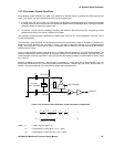
13.2 32kHz Crystal Oscillator
The 32kHz Crystal Oscillator will operate with a standard watch crystal (32768Hz = 2
15
Hz). It is based on a Pierce
Oscillator Cell, (Refer to Section 14.3 "Processor Crystal Oscillator" on page 137, for more information). The
oscillator output is via a buffered Schmitt trigger, which provides a square wave, which is compatible with the
dividers, counters and registers in the Real Time Clock cell.
The Pierce oscillator relies on a resistor to provide negative feedback, which is set by a resistor. The 32kHz
oscillator requires a resistor of high value (10MΩ), and is needed externally to the GP4020. A 32kHz crystal has a
high Effective Series Resistance (ESR), in the region of 40kΩ. The nominal loading capacitors C1 and C2 for the