


15: 1PPS Timemark Generator
160 GP4020 GPS Baseband Processor Design Manual
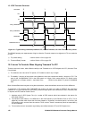
6) The Timemark delay counter will continue counting down to 0, at which point the TIMEMARK output register
will be cleared and the counter will stop.
7) At the next Timemark event, the same delay value will be used in the Timemark delay counter, unless a new
value has been programmed in. The value of TIM_DEL_LO MUST be set before programming the
TIM_DEL_HI register. Failure to do this will NOT allow the Timemark delay counter to be loaded with the
correct value, and the counter will NOT function.
It should also be noted that the Timemark Delay Counter output is only set if the counter = 40000. If step 2 above
loaded a value equivalent to less than 1ms, TIMEMARK would not be set.
This method means that the TIC period can be kept constant. Therefore, the software to run this counter should
only have a minimal impact on the GPS function.
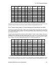
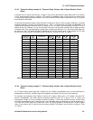
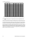
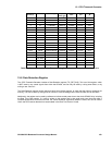
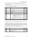
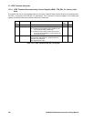
15.5.2 Timemark setting example 5 - Timemark Delay Counter with No Receiver Clock Offset
It is assumed that the Receiver Clock Reference (i.e. TCXO for RF Front-end) has a zero offset. To automatically
correct the timing of 10 cycles of TIC for each Timemark output pulse from 999999µs, to 1.000000s, the 1PPS
Timemark generator needs to add a 1µs delay to the Timemark output. This delay will need to be incremented by
1µs for each Timemark output, until the delay period is greater than or equal to the TIC period. If the calculated
delay is greater than or equal to the period of 1 TIC, when the Counter delay can be rolled over, a TIC can be
skipped by withholding the RAW_Timemark pulse from the correlator. In this instance, the TIC skip will occur once
every 1,000,000 TICs (approx. every 27.7 hours).
The default TIC period would need to be set to 99999.9µs, (PROG_TIC_HIGH + PROG_TIC_LOW would be set
with 0x08B823), TIM_DEL_ENAB would be set to '1', and the initial delay required would be 1µs, achieved by 40
M_CLK cycles of 25ns. TIM_DEL_LO is set to be 40,040 or '0x9C68' (40,000 for the 1ms pulse period required),
and TIM_DEL_HI is set to '0', although the register should be programmed with a default 0x40 to enable the
Timemark delay counter. The process would occur, as shown in Table 15.5 below.
Timemark
Event (s)
TIC
Event
TIC Time (s)
Required
delay (µs)
TIM_DEL
value
TIM_DEL
_LO
TIM_DEL
_HI
0 0 0 0 40000 0x9C40 0x40
1 10 0.999999 1 40040 0x9C68 0x40
2 20 1.999998 2 40080 0x9C90 0x40
3 30 2.999997 3 40120 0x9CB8 0x40
100 1000 99.999900 100 44000 0xABE0 0x40
101 1010 100.999899 101 44040 0xAC08 0x40
638 6380 637.999362 638 65520 0xFFF0 0x40
639 6390 638.999361 639 65560 0x0018 0x41
1000 10000 999.999000 1000 80000 0x3880 0x41
1001 10010 1000.998999 1001 80040 0x38A8 0x41
10000 100000 9999.990000 10000 440000 0xB6C0 0x46
10001 100010 10000.989999 10001 440040
99999 999990 99998.900001 99999 4039960 0xA518 0x7D
(SKIP TIC) 1000000 99999.900000 100000 4040000
0xA540 0x7D
100000 1000001 99999.9999999 0.1 40004 0x9C44 0x40
100001 1000011 100000.9999989 1.1 40044 0x9C6C 0x40
Table 15.5 TIC delay calculations for Timemark, using Delay Counter - TIC period with zero error