


15: 1PPS Timemark Generator
GP4020 GPS Baseband Processor Design Manual 163
Timemark
Event (s)
TIC Event TIC Time (s) Required
delay (µs)
TIM_DEL
value
TIM_DEL
_LO
TIM_DEL
_HI
0 0 0 0 40000 0x9C40 0x40
(TIC ADD)
1 9 0.90000135 99998.65 4039946 0xA50A 0x7D
2 19 1.90000285 99997.15 4039886 0xA4CE 0x7D
3 29 2.90000435 99995.65 4039826 0xA492 0x7D
100 999 99.90014985 99850.15 4034006 0x8DD6 0x7D
101 1009 100.90015135 99848.65 4033946 0x8D99 0x7D
1000 9999 999.9014999 98500.15 3980006 0xBAE6 0x7C
1001 10009 1000.90150135 98498.65 3979946 0xBAAA 0x7C
10000 99999 9999.91499985 85000.15 3440006 0x7D86 0x74
10001 100009 10000.91500135 84998.65 3439946 0x7D49 0x74
66666 666659 66665.99999885 1.15 40046 0x9C6E 0x40
(TIC ADD)
66667 666668 66666.9000002 99999.8 4039992 0xA538 0x7D
66668 666678 66667.9000017 99998.3 4039932 0xA4FC 0x7D
66669 666688 66668.9000032 99996.8 4039872 0xA4BF 0x7D
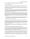
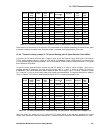
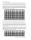
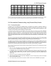
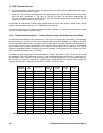
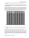
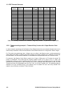
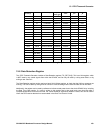
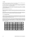
Table 15.8 TIC delay calculations for Timemark, using Delay Counter - TIC period with -2.5ppm error
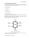
15.6 Data Retention Register
The 1PPS Timemark Generator includes a Data Retention register (TIC_RET[15:8]). This is an 8-bit register, which
is NOT reset by any control signals from within the GP4020, and can only be reset by a chip power failure, or by
writing a new value to it.
The Data-Retention register can be used as a basic 8-bit UIM test register, to check that the UIM bus accesses are
working. This can be done by writing an 8-bit number to it and checking that the same number can be read back.
Additionally, the register can be used by software to indicate a total power-loss to the whole GP4020 chip, including
the Real Time Clock section. If a value is written to the register that is then read back some time later after a
complete power-failure event has occurred, the values should be significantly different. Hence, this can be used to
inform the GPS receiver that the time accumulated in the Real Time Clock is invalid.