


12: Peripheral Control Logic
GP4020 GPS Baseband Processor Design Manual 121
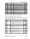
GPIO output line
number
Alternative signal multiplex Condition
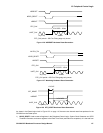
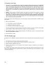
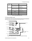
0 BSIOCLK BSIO_MUX[1:0] = '10', '01', '11'
SIGN 1
Not available in standard operation
UIM_TEST = '1'
(i.e. TEST = High
TESTMODE = High)
1 BSIODATA BSIO_MUX[1:0] = '10', '01', '11'
MAG 1
Not available in standard operation
UIM_TEST = '1'
(i.e. TEST = High
TESTMODE = High)
2 BSIOSS[0] BSIO_MUX[1:0] = '01', '11'
3 BSIOSS[1] BSIO_MUX[1:0] = '10', '11'
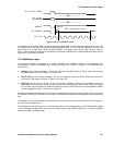
4 DISCIP1 input to Correlator Always connected
5 DISCOP output from Correlator DISCOP_MUX = '1'
6N/A
7 PLLDT1 output UIM_TEST = '1'
Table 12.3 GPIO pin signal multiplex options
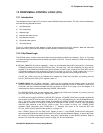
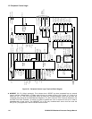
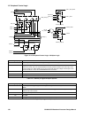
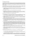
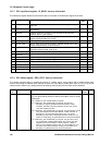
12.5 Interrupt and Wake-up logic
The Interrupt and Wake-up logic block of the Peripheral Control Logic block is used to create a single interrupt line
to the Firefly MF1, from a number of interrupt sources. It also sets up the hardware for a number of Wake-up-from-
Sleep events. The logic used to set-up these two facilities is shown in Figure 12.11 below.
WATCH_INT
MEAS_INT
ACCUM_INT
UART_INT
WAK_COR
WAK_UART
RTC_CMP_INT
RCMP_INT_EN
POWER_GOOD
POW_INT_EN
TIC_INT
PER_INT
DISCIP1
WAK_DISC
NRESET
NSLP_RESET
Figure 12.11 Peripheral Control Logic - Peripheral Interrupt and Wake-up control logic