


14: System Clock Generator
GP4020 GPS Baseband Processor Design Manual 145
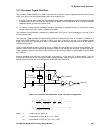
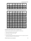
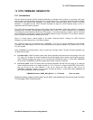
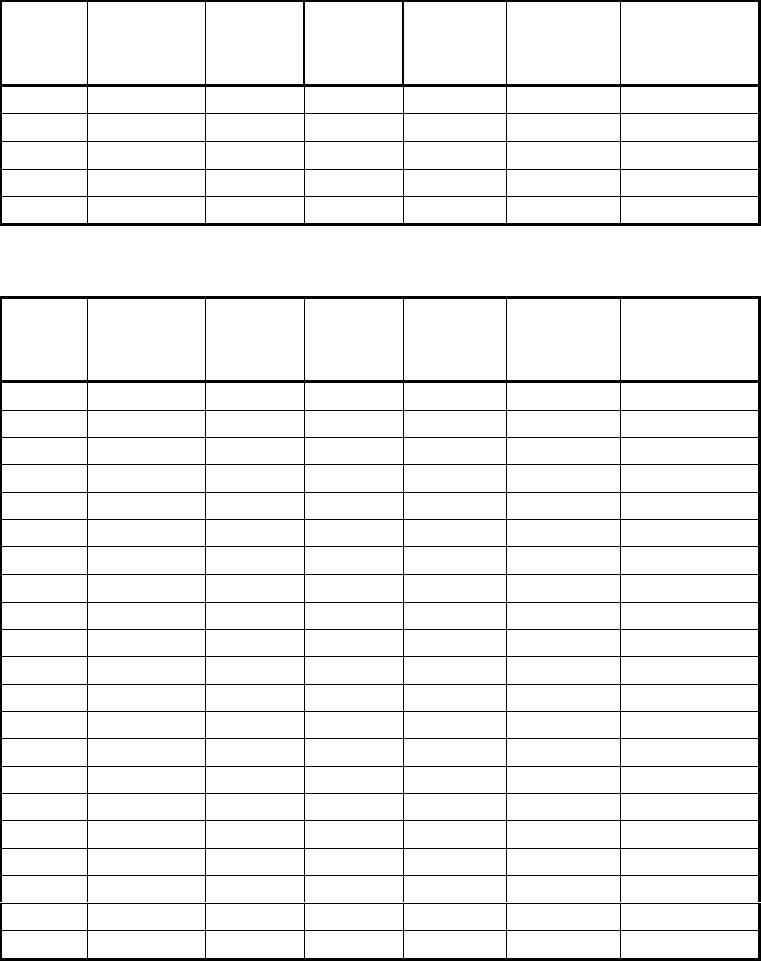
PLL
Mult
Factor
Desired PLL
output
frequency
Prog.
Divider
Control
DIV[4:0]
PLL
SYNC
MODE
SYNCEN
Charge
Pump
setting
CHP[4:0]
VCO Freq.
Range
VCOD[1:0]
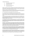
Worst case
settling time.
(µs)
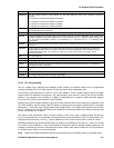
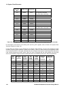
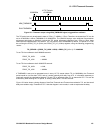
8 40-125MHz 00110 0 01011 01 38
9 40-125MHz 00111 0 01100 01 36
10 40-125MHz 01000 0 01101 01 35
11 40-125MHz 01001 0 01111 01 32
12 40-125MHz 01010 0 10000 01 31
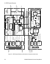
Table 14.5 PLL configuration options with input freq. from Processor Crystal Oscillator … 1
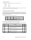
PLL
Mult
Factor
Desired PLL
output
frequency
Prog.
Divider
Control
DIV[4:0]
PLL
SYNC
MODE
SYNCEN
Charge
Pump
setting
CHP[4:0]
VCO Freq.
Range
VCOD[1:0]
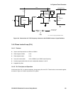
Worst case
settling time.
(µs)
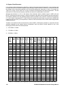
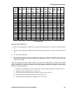
5 80-250MHz 00011 0 00100 00 81
6 80-250MHz 00100 0 00100 00 81
7 80-250MHz 00101 0 00101 00 67
8 80-250MHz 00110 0 00101 00 67
9 80-250MHz 00111 0 00110 00 58
10 80-250MHz 01000 0 00111 00 52
11 80-250MHz 01001 0 00111 00 52
12 80-250MHz 01010 0 01000 00 47
13 80-250MHz 01011 0 01000 00 44
14 80-250MHz 01100 0 01001 00 44
15 80-250MHz 01101 0 01010 00 41
16 80-250MHz 01110 0 01011 00 38
17 80-250MHz 01111 0 01011 00 38
18 80-250MHz 10000 0 01100 00 36
19 80-250MHz 10001 0 01101 00 35
20 80-250MHz 10010 0 01101 00 35
21 80-250MHz 10011 0 01110 00 33
22 80-250MHz 10100 0 01111 00 32
23 80-250MHz 10101 0 01111 00 32
24 80-250MHz 10110 0 10000 00 31
25 80-250MHz 10111 0 10001 00 30
Table 14.5 PLL configuration options with input freq. from Processor Crystal Oscillator … 2
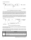
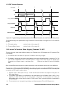
14.5 System Clock Generator Power Consumption issues
The power consumed by the System Clock Generator is dependent on a number of factors:
1) Processor Crystal Oscillator Block; enabled or disabled
2) 40MHz Differential Input Block; enabled or disabled
3) PLL block; enabled or disabled
4) Input frequency and division ratio of the UART_CLK divider block, after the PLL; the higher the input frequency
and the higher the output frequency, the more current consumed.