


1: Introduction
GP4020 GPS Baseband Processor Design Manual 3
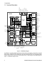
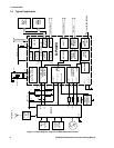
1.3.1 ARM
Processor (ARM7TDMI)
The ARM7TDMI is a 32-bit RISC microprocessor core designed by Advanced RISC Machines (ARM). It uses a
series 7 microprocessor Core, with the following functional extensions:
• Thumb (16-bit) instruction set
• Debug interface-using J-TAG.
• Fast Multiplier
• Embedded In-Circuit-Emulation capability
The ARM7TDMI is object-code compatible with all earlier ARM6 and ARM7 based products. The ARM7TDMI is a
fully static design and as such consumes dynamic power only when clocked.
Details on the ARM7TDMI can be found in:
a) Section 3 "ARM7TDMI MICROPROCESSOR" on page 19 of this manual
b) Firefly MF1 Core Design Manual, (DM5003), also available from Zarlink Semiconductor
c) ARM7TDMI Technical Reference Manual (document reference ARM DDI 0029F), which is downloadable (1.7
MB PDF) from ARM's website http://www.arm.com. The documentation download page can be found at:
http://www.arm.com/arm/documentation?OpenDocument .
1.3.2 Boot ROM
The GP4020 BOOT ROM contains code, which is executed every time there is a complete system reset (i.e. when
main power has been removed from the GP4020).
The code installed on the BOOT ROM, allows the GP4020 to undertake either of 2 functions after a complete reset:
• Run External FLASH EPROM from EPROM base address user to either run code direct from an external
FLASH EPROM memory
• Load into the internal SRAM a unique program via the UART1 input. This could be used for test purposes,
although the target use of this facility is to allow for field-upgrades of GPS receiver firmware, in conjunction
with a FLASH EPROM.
Details can be found in section 4 "BOOT ROM" on page 27:
1.3.3 BµILD Bus
This is a modular bus architecture and specification, via which all on-chip modules communicate with each other.
These modules can either be bus masters or slaves. A bus master can initiate a bus access, generate addresses
and control read or write transfers. A bus slave responds to a bus master request when selected by the system
address decoder, and may, if required, assert a wait signal on the bus until the relevant data transfer has been
completed. All internal data transfers on the module bus are single cycle.
The Firefly MF1 micro-controller has three modules that are capable of operating as Bus masters. These are the
ARM7TDMI Core, DMAC and SSM, described below.
1.3.4 BµILD Serial Input Output (BSIO)
This module produces a 2-channel 3-wire serial interface for upto 2 external "Slave" serial interface devices (e.g.
serial EEPROM). It provides both MICROWIRE
TM
Interface and Serial Peripheral Interface (SPI
TM
) compatibility.