


7: 12-Channel Correlator
52 GP4020 GPS Baseband Processor Design Manual
operations to the code and carrier DCO’s are 32-bit data transfers, in which the High 16-bit word must be written
immediately before the low 16-bit word. Note that the write cycle to write cycle delay of 300ns referred to in the
Microprocessor Interface does not apply between the first and second write cycles for 32-bit DCO data transfers.
For further information, refer to Section 7.5 "12 Channel Correlator Interface Timing" on page 63.
7.1.8 UIM Interface
The UIM Interface performs data conversion and re-timing between the 12-channel correlator (clocked with the
M_CLK signal from the System Clock Generator), and the Up Integration Module Bus (UIM bus), clocked by
BµILD_CLK. For further information, refer to Section 11 "MEMORY PERIPHERAL CONTROLLER (MPC)" on page
109.
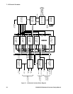
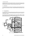
7.2 Tracking Modules
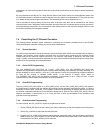
The Tracking Modules are 12 identical signal-tracking channels numbered CH0 to CH11, each with the block
diagram shown in Figure 7.2 below. These blocks generate the data used to track the satellite signals. There is no
overwrite-protection mechanism on this data. For further information, refer to Section 7.4 "Controlling the 12
Channel Correlator" on page 59.
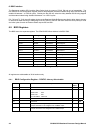
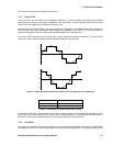
Each Tracking Channel can be individually programmed to operate in either UPDATE or PRESET mode. Update
mode is the normal mode of operation. PRESET mode is a special mode of operation where writes to certain
registers are delayed until the next TIC to allow synchronisation of registers and pre-setting of the code DCO
phase. For further information, refer to Section 7.4.9 "PRESET Mode" on page 61.
CARRIER
DCO
CARRIER
CYCLE
COUNTER
C/A CODE
GENERATOR
16 BIT ACCUMULATE AND
DUMP - Q PROMPT
16 BIT ACCUMULATE AND
DUMP - Q TRACKING
16 BIT ACCUMULATE AND
DUMP - I PROMPT
16 BIT ACCUMULATE AND
DUMP - I TRACKING
CODE
DCO
CODE
SLEW
EPOCH
COUNTERS
CODE PHASE
COUNTER
DUMP CONTROL SIGNAL
DATA BUS
SIGN0
AND
MAG0
I
LO
Q
LO
DUMP
SIGN1
AND
MAG1
SOURCE
SELECTOR
SOURCE &
MODE
SELECT
Figure 7.2 Tracking Module Block Diagram