iv GP4020 GPS Baseband Processor Design Manual
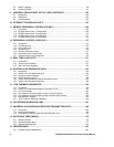
8.3 DMAC Triggering................................................................................................................ 99
8.4 Cautionary Notes.............................................................................................................. 101
9 GENERAL PURPOSE INPUT OUTPUT (GPIO) INTERFACE ....................................... 103
9.1 Introduction ...................................................................................................................... 103
9.2 Initialisation ...................................................................................................................... 105
9.3 GPIO Registers ................................................................................................................ 105
10 INTERRUPT CONTROLLER (INTC) ............................................................................. 107
11 MEMORY PERIPHERAL CONTROLLER (MPC) .......................................................... 109
11.1 Introduction ...................................................................................................................... 109
11.2 GP4020 Memory Area 1 Configuration .............................................................................. 109
11.3 GP4020 Memory Area 2 Configuration .............................................................................. 110
11.4 GP4020 Memory Area 3 Configuration .............................................................................. 111
11.5 GP4020 Memory Area 4 Configuration .............................................................................. 112
12 PERIPHERAL CONTROL LOGIC (PCL)....................................................................... 113
12.1 Introduction ...................................................................................................................... 113
12.2 Chip Reset Logic.............................................................................................................. 113
12.3 PLL Enable Logic ............................................................................................................. 118
12.4 Multiplex Logic.................................................................................................................. 119
12.5 Interrupt and Wake-up logic .............................................................................................. 121
12.6 Chip-wide Power Control modes ....................................................................................... 123
12.7 Peripheral Control Logic Registers .................................................................................... 124
13 REAL TIME CLOCK (RTC)........................................................................................... 131
13.1 Introduction ...................................................................................................................... 131
13.2 32kHz Crystal Oscillator.................................................................................................... 131
13.3 Real Time Clock Registers................................................................................................ 132
14 SYSTEM CLOCK GENERATOR (SCG)........................................................................ 135
14.1 Introduction ...................................................................................................................... 135
14.2 40MHz Low Level Differential Input ................................................................................... 136
14.3 Processor Crystal Oscillator.............................................................................................. 137
14.4 Phase Locked Loop (PLL)................................................................................................. 139
14.5 System Clock Generator Power Consumption issues......................................................... 145
14.6 System Clock Generator Registers.................................................................................... 146
15 1PPS TIMEMARK GENERATOR.................................................................................. 149
15.1 Introduction ...................................................................................................................... 149
15.2 Issues To Consider When Aligning Timemark To UTC....................................................... 152
15.3 UTC Error Budget............................................................................................................. 153
15.4 Fine-resolution Timemark setting, using TIC period slewing ............................................... 155
15.5 Fine-resolution Timemark setting, using Timemark Delay Counter...................................... 159
15.6 Data Retention Register.................................................................................................... 163
15.7 1PPS Timemark Generator Registers................................................................................ 164
16 UP-INTEGRATION MODULE (UIM).............................................................................. 167
17 UNIVERSAL ASYNCHRONOUS RECEIVER TRANSMITTER (UART) ......................... 169
17.1 Introduction ...................................................................................................................... 169
17.2 Baud Rate Generation ...................................................................................................... 169
17.3 Connections to the BµILD bus and the Firefly MF1 Core .................................................... 174
18 WATCHDOG TIMER (WDOG) ...................................................................................... 176
18.1 Design Features ............................................................................................................... 176
18.2 Operational Description..................................................................................................... 177
18.3 Watchdog Register Map.................................................................................................... 178
19 ADDRESS MAPS.......................................................................................................... 181
19.1 GP4020 System Address Map .......................................................................................... 181


