


7: 12-Channel Correlator
GP4020 GPS Baseband Processor Design Manual 89
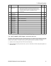
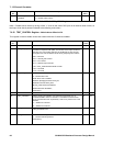
7.6.33 TIMEMARK_CONTROL Register - Write Address Offset 0x1EC
This register is used to set-up the correlator part of the 1PPS Timemark Generator (i.e. the Raw_Timemark
Generator). The RAW TIMEMARK Generator operates in one of two ways:
1) Armed mode. In Armed mode setting the ARM_TIMEMARK bit arms the RAW TIMEMARK generator which
subsequently produces a RAW TIMEMARK output pulse coincident with the next rising edge of TIC. This then
resets the ARM_TIMEMARK bit ready for a new arming sequence in the future.
2) Free-run mode. In Free–run mode, enabled by setting the FREE_RUN_TIMEMARK bit High, the
ARM_TIMEMARK bit is disabled. A RAW TIMEMARK pulse is produced coincident with the first rising edge of
TIC after the FREE_RUN_TIMEMARK bit has been set, and then on an integer number of TICs determined by
the FREE_RUN_RATIO bits. In free run mode the TIMEMARK period is:
TIMEMARK Period = (FREE_RUN_RATIO + 1) * TIC Period
The RAW_TIMEMARK signal is then used by the 1PPS Timemark Generator, in conjunction with software to
produce a UTC aligned 1PPS output, down to a resolution of 25ns. The RAW_TIMEMARK generator can also
produce a 1PPS output without the assistance of the 1PPS Timemark generator, but the resolution of the Timemark
will be 175ns which is often considered too slack for high precision time-keeping.
In the GP4020, RAW_TIMEMARK can be accessed through:
1) DISCOP, if the SYSTEM_SETUP register is configured to output RAW_TIMEMARK, and DISCOP_MUX in the
PCL IO_REV register is set to output DISCOP onto GPIO[5] (pin 93 (100-pin package));
2) TIMEMARK (pin 69 (100-pin package)), if TIC_CORR[2:0] in TIC_RET register (PCL Block) is set to '000'.
Refer to Section 15 "1PPS TIMEMARK GENERATOR" on page 149 for more information.
Bit
No.
Mnemonic Description Reset
Value
R/W
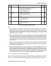
15:7
Not used
-W
6:2 FREE_RUN_RATIO[4:0] 5-bit Ratio value used to set repetition rate of FREE_RUN mode Raw
Timemark events, in terms of numbers of TICs. Range = 1 to 15 TICs
(approx. 100ms to 1.5s, with TIC at approx. 100ms.)
0x00 W
1 FREE_RUN_TIMEMARK '1' = Enable Free Run Timemark. Output Raw Timemark pulses in
multiples of TIC events defined by FREE_RUN_RATIO.
'0' = Enable Armed Timemark mode. Raw Timemark event produced
on the rising edge of TIC following the setting of the
ARM_TIMEMARK bit.
0W
0 ARM_TIMEMARK '1' = ARM RAW Timemark generator which subsequently produces a
RAW TIMEMARK output pulse coincident with the next rising
edge of TIC. ARM_TIMEMARK cleared by Raw Timemark
event.
'0' = no effect.
0W
Table 7.39 CORR TIMEMARK_CONTROL Register
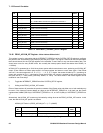
7.6.34 X_DCO_INCR_HIGH Register - Write Address Offset 0x1A4
The X_DCO_INCR_HIGH register may be used to write the high bits for any Carrier or Code DCO in any channel.
A write to X_DCO_INCR_HIGH must always be followed by a write to the appropriate
CHx_CARRIER_DCO_INCR_LOW or CHx_CODE_DCO_INCR_LOW to define the destination and to complete the
action.
Using X_DCO_INCR_HIGH rather than CHx_CARRIER_DCO_INCR_HIGH gives a quicker way of loading the
whole DCO’s values because the _LOW write may follow the X_DCO_INCR HIGH write immediately (without
incurring a 300ns wait). Register structure is identical to the CHx_<>_DCO_INCR_HIGH registers.