


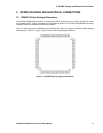
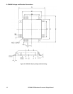
2: GP4020 Package and Electrical Connections
GP4020 GPS Baseband Processor Design Manual 17
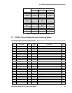
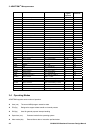
TEST (pin 67) TESTMODE (pin 74) TEST FUNCTION
GND (0) GND (0) Normal Operation
VDD (1) GND (0) Firefly Macrocell test mode
GND (0) VDD (1) Firefly System test mode
VDD (1) VDD (1) UIM Logic test mode
Details of ALL test modes are covered in section 2.10 of the Firefly MF1 Core Design Manual (DM5003),
available from Zarlink Semiconductor.
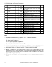
6) NICE (pin 84) and NTRST (pin 90) control a number of operation modes and a debug signal multiplex on pins
86, 87, 88, 89 and 90, as follows:
NICE = Low ARM7TDMI in ICE mode.
ARM7TDMI will not access memory unless instructed to by the JTAG interface. NTRST
(pin 90) set Low will reset the JTAG Interface.
NICE = High ARM7TDMI in Normal mode.
NTRST does not effect a reset on the JTAG interface. However, a reset of Firefly will
also reset the JTAG.
NTRST (pin 90) has a reset and signal-multiplex function, dependent on the state of the NICE input (pin 84):
i) NICE = Low: JTAG debug signals connected to pins 86, 87, 88, 89 & 90, as follows:
Pin 86 = TCK = JTAG clock in
Pin 87 = TDI = JTAG data in
Pin 88 = TDO = JTAG data out
Pin 89 = TMS = JTAG mode select in
Pin 90 = NTRST = Active low reset to JTAG interface
(JTAG interface also reset when Firefly MF1 is reset)
ii) NICE = High and NTRST = High:
This is the Normal mode of operation for GP4020. The System Services Module Broadcast Diagnostic
debug output signals are connected to pins 86, 87, 88, 89 as follows:
Pin 86 = BDIAG[0]
Pin 87 = BDIAG[1]
Pin 88 = BDIAG[2]
Pin 89 = BDIAG[3]
Diagnostic mode must have been set-up using the Diagnostic Configuration Registers within Firefly MF1.
Refer to Section 8 of Firefly MF1 Core Design Manual (DM5003), from Zarlink Semiconductor, for more
information.