


15: 1PPS Timemark Generator
GP4020 GPS Baseband Processor Design Manual 159
TIC
Event
TIC_
CORR
[2:0]
Phase
Offset
Offset
delay
(ns)
Over
flow
Next TIC
Period (µs)
Cumulated
Overflow
Overflow
delay (ns)
Total
Delay
(ns)
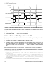
5 001 5 125 0 99999.975 0 0 125
6 001 6 150 0 99999.975 0 0 150
7 001 0 0 1 100000.150 1 175 175
8 001 1 25 0 99999.975 1 175 200
9 001 2 50 0 99999.975 1 175 225
10 001 3 75 0 99999.975 1 175 250
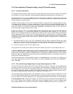
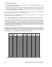
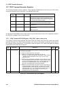
Table 15.4 TIC delay calculations for Timemark using TIC period slew, TIC period with -2.5ppm error
All the TIC events will need to adjust the TIC period. If the Receiver Clock offset appears larger still than -2.5ppm,
the TIC period will need to be further reduced by a further data decrement of the PROG_TIC_LOW register.
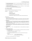
15.5 Fine-resolution Timemark setting, using Timemark Delay Counter
15.5.1 Functional Description
In addition to the TIC slewing logic, described earlier, the GP4020 also includes an alternative method for
generating delays of 25ns resolution to the TIC signal, without needing to change the TIC period. Since TIC is used
to time most functions within the 12-channel correlator, this can be a very useful method for generating a 1PPS
Timemark if the GPS software needs to keep the TIC period constant.
A 22-bit down counter clocked by M_CLK (40MHz) can be used to delay the occurrence of the 1PPS TIMEMARK
output from a TIC event. The range of 2
22
x 25ns, gives a total delay range of upto 104.857575ms (which is slightly
larger than the default TIC period). The Timemark output pulse, which is 1ms wide needs to be derived from the
counter also and therefore, the last 1ms of the down-count is used to generate the Timemark pulse. This is
achieved by setting an output when a down-count reaches 40,000, and then clearing it 1ms later when the count
reaches ‘0’.
The use of a 22-bit counter being clocked at 40MHz will consume more power than using the TIC period slewing
technique highlighted earlier. However, it will allow 1PPS Timemark to be implemented as an add-on to the GPS
function, rather than needing to consider the impact of variable TIC periods on the GPS function.
To enable the Timemark Delay Counter and disable the TIC Slewing logic, set the TIM_DEL_ENAB bit (bit 6) of the
TIM_DEL_HI register. This action enables a 40MHz clock to the delay counter, and transfers the counter output to
the TIMEMARK output pin, in place of the output from the TIC slewing Timemark delay logic. The value used to set
the down-count in the 22-bit down-counter is applied via the TIM_DEL_LO and TIM_DEL_HI registers.
When using the Timemark delay Counter to produce a delay that aligns Timemark to UTC, the sequence of events
would be as follows:
1) After a TIC event, the software should decide if RAW_TIMEMARK should be set at the next TIC event, and if
so, by how much the TIMEMARK output should be delayed.
2) If TIMEMARK output is to be generated, the software should load the Timemark counter delay with a delay
1ms greater than the desired delay. The value of TIM_DEL_LO MUST be set before programming the
TIM_DEL_HI register. Failure to do this will NOT allow the Timemark delay counter to be loaded with the
correct value.
3) At the next TIC event, the hardware will set RAW_TIMEMARK.
4) At the first positive edge of M_CLK after RAW_TIMEMARK is set, the Timemark delay counter will be loaded
with the value specified in step 2.
5) The Timemark delay counter will then count down to 40000. It will then set the TIMEMARK output register.